John Bidwell - January 1, 2024
The future is back.
Mankind has come a long way during the past few centuries, and now, because of the most recent technological achievements of my own inventions (WCSG technology, Fig. 1), we can no longer ignore the many truths that directly link the implementation of high voltage science to our ancient past. From showing how a lingam is indeed an extreme, high-voltage, high-amperage water-cooled spark gap, to some of the ancient practical uses it had, this will be the first paper in our current civilization detailing the basic functionality of an SGL (Spark Gap Lingam, Fig. 2), explain it's primary use as an electromagnetic flux engine, and show how this technology can be applied in our own fast-paced, high-voltage world of today along with where it most-certainly will at some point be implemented into the future of our tomorrow.
After decades and countless personal hours spent studying over ancient global histories, observing all their archeological and unmistakable, similar architectures (which also directly connect ancient sites together around the world throughout every known time period), I have come to the incredible conclusion as to what part of this mystery the lingam represents and without a doubt, have also demonstrated the high science and application of this advanced technology - for it simply cannot be denied that SGL's are a part of an elegant electrical machine - and they were obviously used for electromagnetic flux / power regulation which is harnessed for several purposes; all of which and more can be applied to benefit today's growing technological societies.
The system is comprised of 6 main components.
Component overview "Fig 4"
1) Trident PFR (Positive Flow Receiver)
2) IEA (Intermediary Electrode Array)
3) GFE (Ground Flow Emitter)
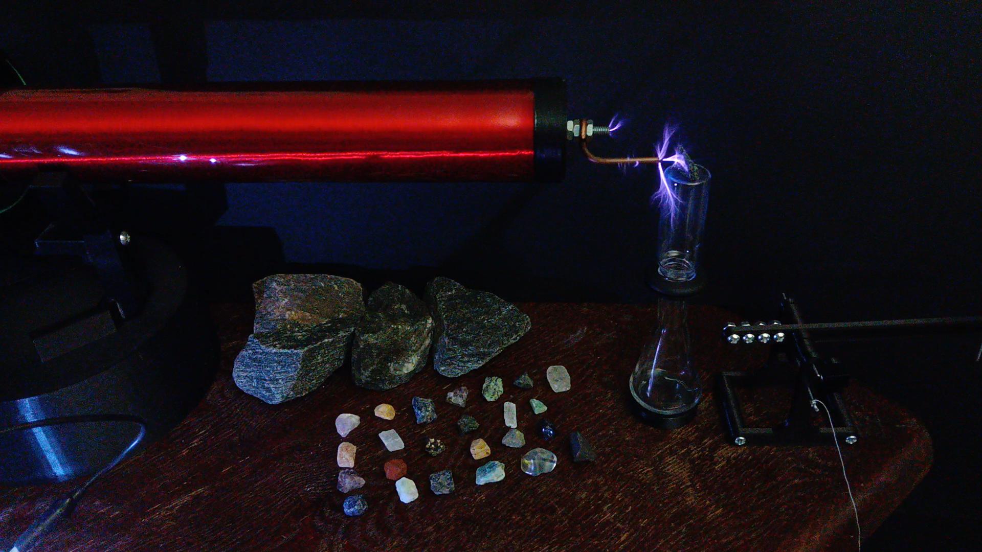
4) Lingam stone
5) Non-conductive water bowl, reservoir or surface
6) Trident holder / adjustment mechanism
I've found the best materials observed so far are the same used across countless ancient temples (mostly India), which is copper or brass for the Trident PFR (Positive Flow Receiver), a copper, brass or even gold IEA (Intermediary Electrode Array) and steel would seem, to date as of testing, the better material for a GFE because of both its electromagnetic and thermal properties (other metals are also observable being used here, however note that copper does not make an ideal GFE).
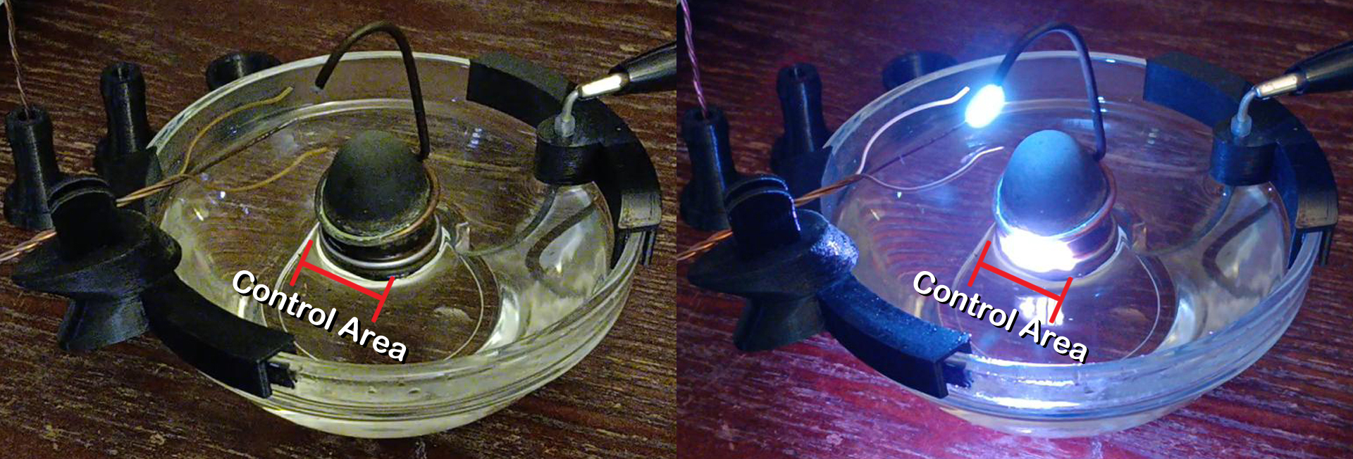
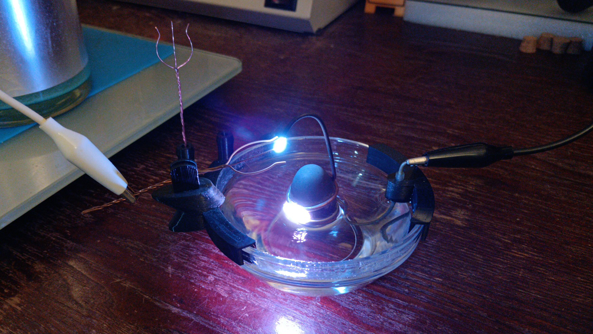
The methodology of implementing an SGL is by first positioning the IEA over the lingam stone. This is achieved by tilting the lower electrode ring so that it rests at a desired angle and distance congruent to the GFE (Fig. 5) which creates a control area (Fig. 6); this is a key element of an SGL's operation as the adjustment here directs the primary point at which voltage is regulated before flowing through the rest of the system.

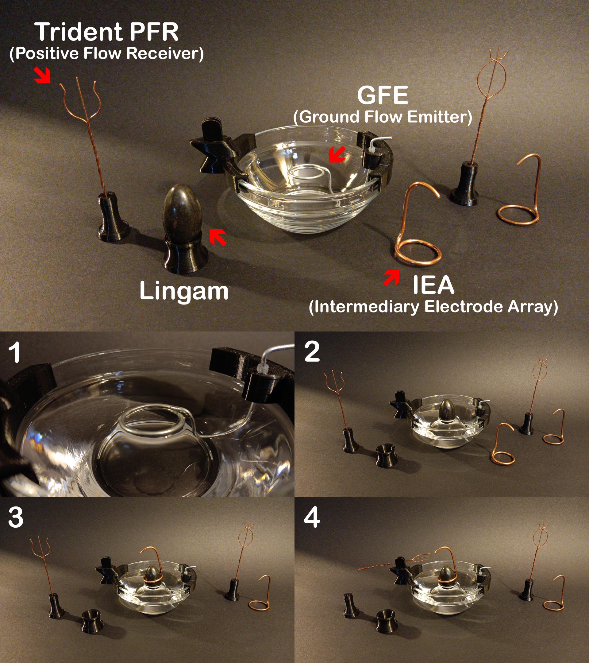
1) Fill up the water reservoir until water is only touching the lower GFE ring level.
2) Place your lingam stone securely onto the GFE ring (rotate until there is a fit) and recheck that water is only touching the lower part of the GFE and not at or above the ring's top level.
3) Position the Intermediary Electrode Array onto the lingam stone, making sure to both distance and tilt it at high enough of an angle so that sparks emitted are contained in a projected control area (Fig. 11) on the corresponding GFE ring (usually away from the rear ground wire). Be certain that the rear of the IEA is also angled at a high enough distance away from the rear GFE's bottom ring than at your desired control area, or it can spark at this unfavorable location. The ideal distance between the IEA and your projected control area is approximately 3.5 - 6 millimeters for an SGL at this size and scale.
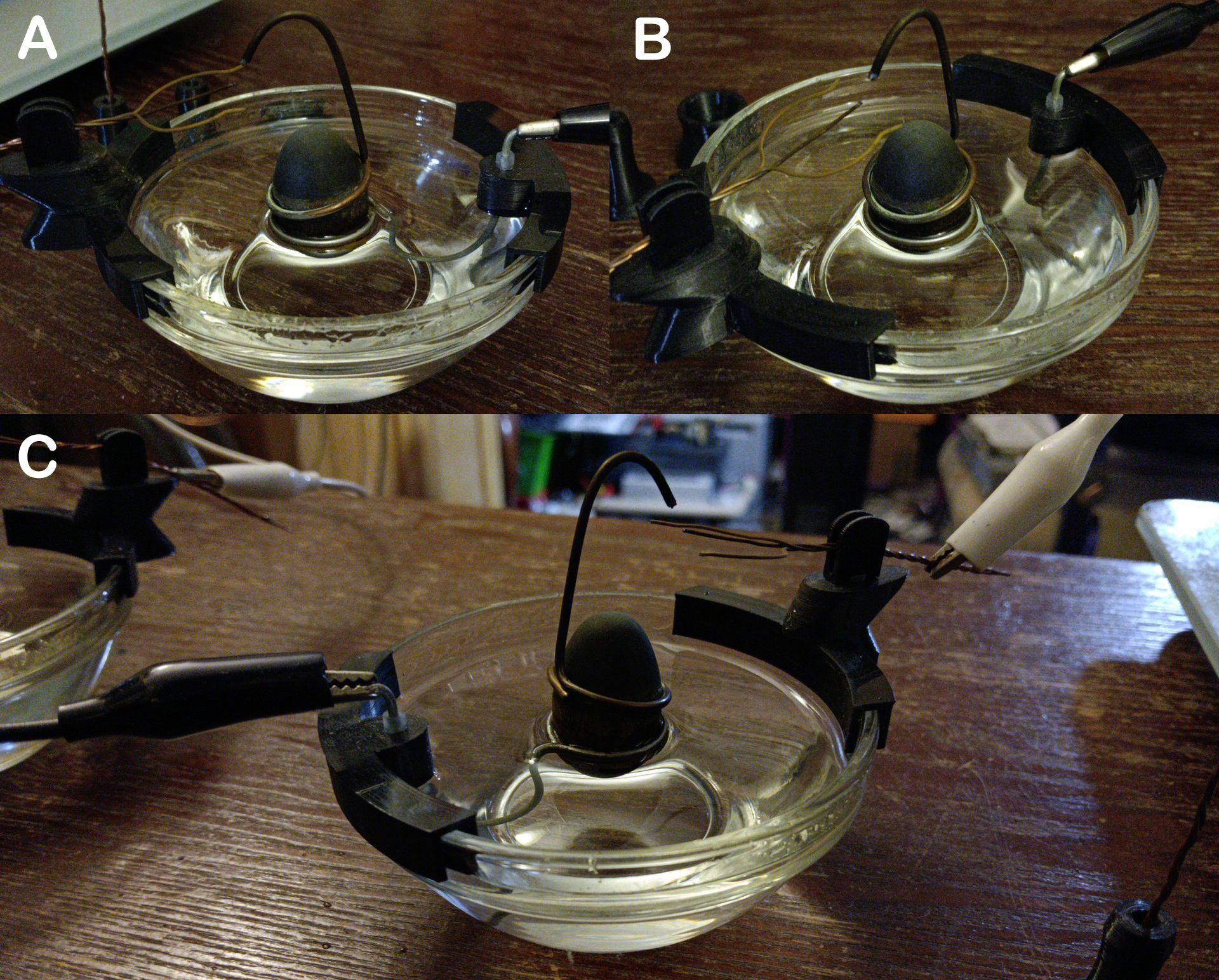
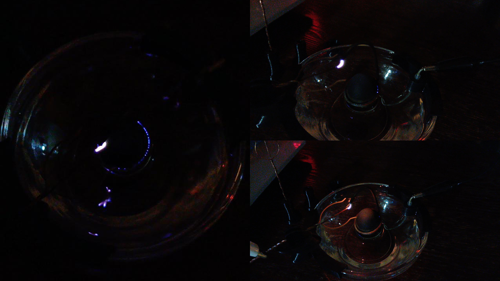
5) Power on the system briefly. The first few firings of an SGL right after setting up a fresh system will usually quickly ground out until either there is enough water between the lingam stone and lower GFE ring (water must both saturate this location and move slightly up the lingam walls before it will run reliably); an effect of which is naturally attained by current moving throughout the system while it's running, and why a fresh setup must more-than-likely be pre-fired or even adjusted possibly several times.
You can see some of the more common setup failures in the pictures below (Fig. 13), caused by either improper water levels, electrode misalignment or too much amperage being applied. The first few firings of a freshly setup lingam may resemble these illustrated failures, however do not get discouraged, and do not allow the electrodes to burn for any longer than is required to restart.
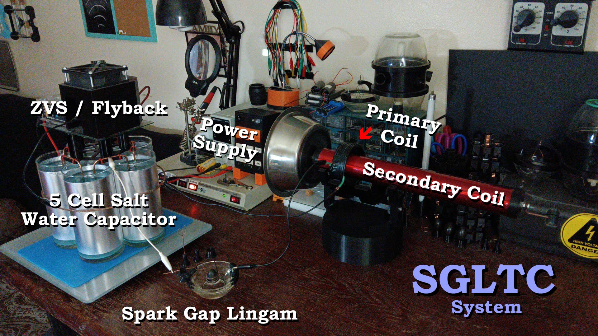
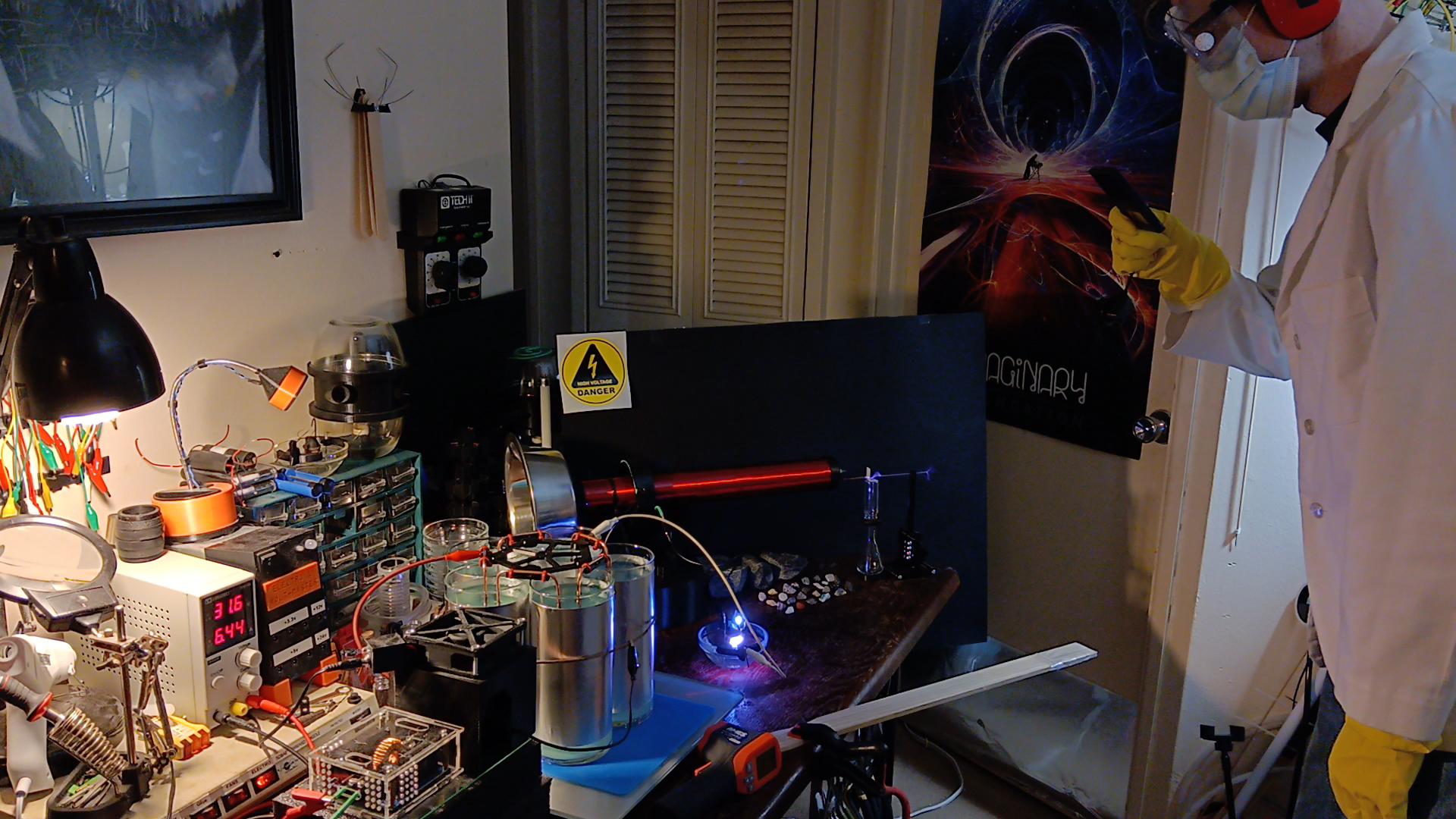
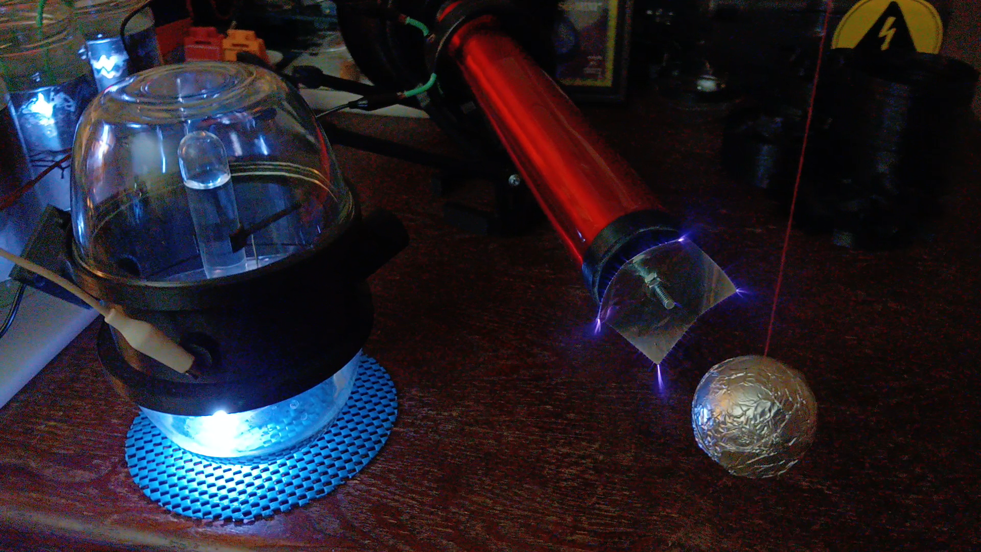
The power of an SGL can be harnessed in many ways, one of which is when integrated into a Tesla coil system. An 'SGLTC' (Fig. 15), or 'Spark Gap Lingam Tesla Coil' is in fact a new type of Tesla coil, one we now as a civilization have an exciting ability to explore. The following pictures are of a quick overview for setting up an SGLTC - and the next step up, a 'Double Primary Spark Gap Lingam Tesla Coil' (Fig. 16), or the 'DPSGLTC' for short...
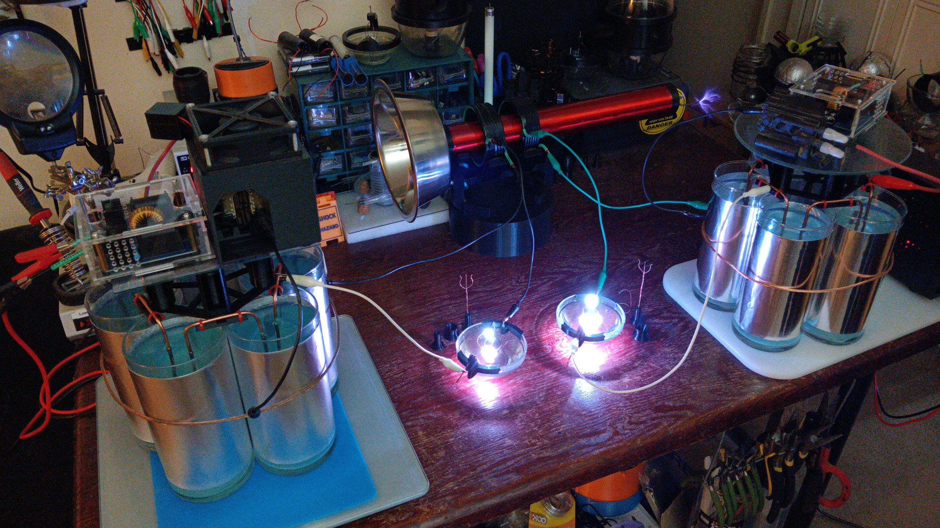
By applying a high-voltage, high-amperage current supplied through lower capacitance, a true ungodly amount of voltage can be then fluctuated throughout the SGL and its connected systems (Fig. 17). A thermal balance is achieved in many ways and by several factors, mainly, the continual cooling / thermal dissipation of the GFE by water, in conjunction with the superpositioned IEA above, as it is named, which functions as an Intermediary Electrode Array. This array acts as a kind of 'buffer zone' between the GFE negative and the positive receiver; it is this 'buffer zone' which takes the majority of abusive heat generated by an active system and why these main types of stones found in ancient lingams, such as granite, are the types used and needed to help maintain the adjustable hot IEA in place during operation.

DISCUSSION

...Thank you and volt on, my friends!
Links
How a Water-cooled Spark Gap Works
https://www.youtube.com/watch?v=mjeaYCkkxnI
Radiant Energy Demonstration
https://www.youtube.com/watch?v=XrcThBgGiCc
The Greatest Mystery, Solved.
https://www.youtube.com/watch?v=n8hRsg8tWXg
How a Spark Gap Lingam Works
https://www.youtube.com/watch?v=91cjP0m-dtU
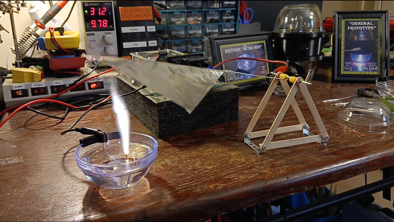
Bidwell's Bird - A Brand-new Science Experiment
https://www.youtube.com/watch?v=bY8FVpOmw5Y
Bidwell's Bee - Another New Science Experiment
https://www.youtube.com/watch?v=tOct273eW0k
This website
https://www.WCSG-Science.com
Kickstarter WCSG-Mini campaign
https://www.kickstarter.com/projects/johnbidwell/wcsg-mini
Kickstarter SGL campaign
https://www.kickstarter.com/projects/johnbidwell/spark-gap-lingam-sgl