Online Instruction Manual
HARDWARE REQUIRED
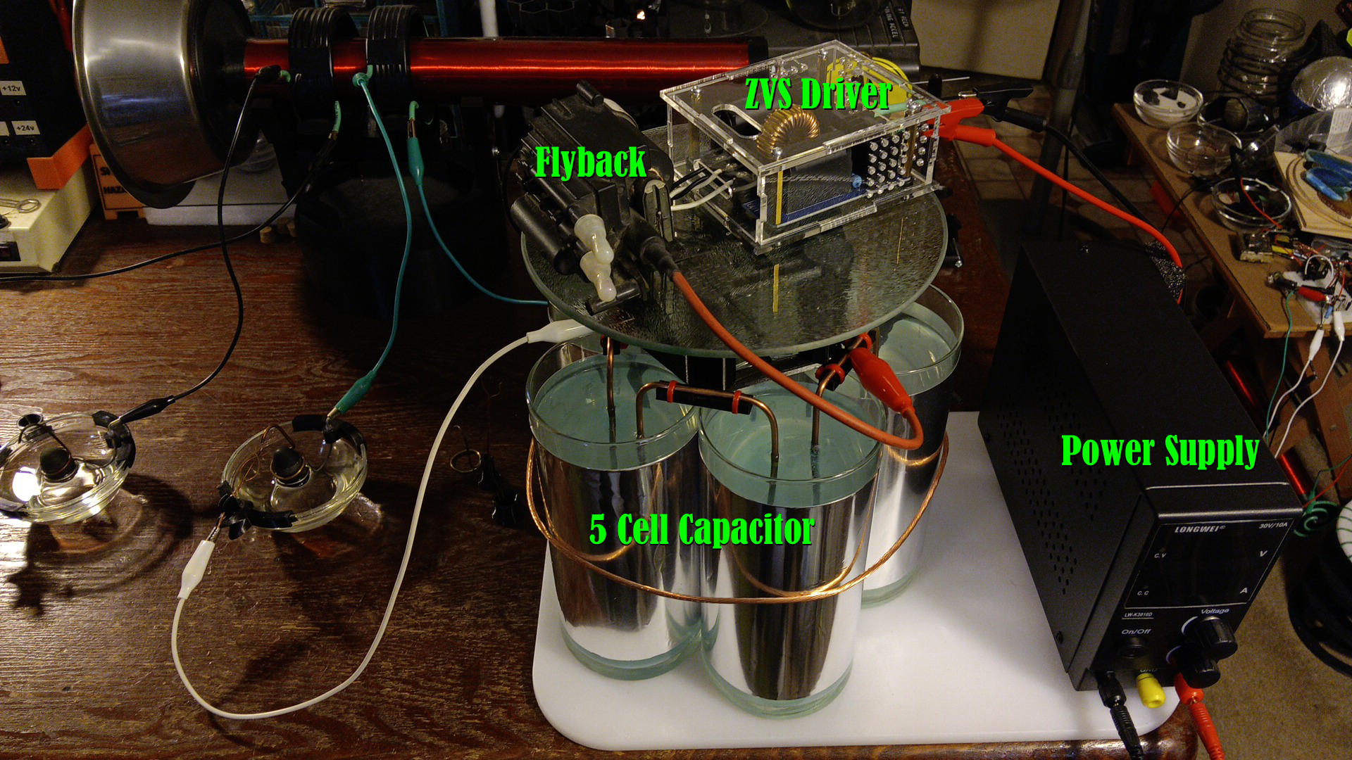
The recommended hardware required to run this small-scale SGL is:
• ZVS driver / 30v, 10A
• Flyback transformer with an output of about 30,000+ volts
• A variable power supply capable of 30 volts, 10 amps
• High-voltage / high amperage capacitors (recommended 5-8 cell saltwater capacitors)
• 18 to 16 gauge wires for efficiently moving high current throughout the system
SAFETY
Never look directly at the spark gap without the proper eye protection - use an arc welder's mask or goggles of at least SHADE 9. Sunglasses just won't do.
ALWAYS either disconnect, ground out or discharge your capacitors before making adjustments to the electrodes or working on the system. *Salt water capacitors sometimes need to be kept grounded for at least 3 full seconds to dissipate all of their charge!
Ozone: As with any high-voltage application, spark gaps emit dangerous levels of ozone that must adequately be ventilated at all times. Be sure to always have fresh air moving through your workspace.
OPERATION / SETUP
The basic steps for setting up your SGL are:
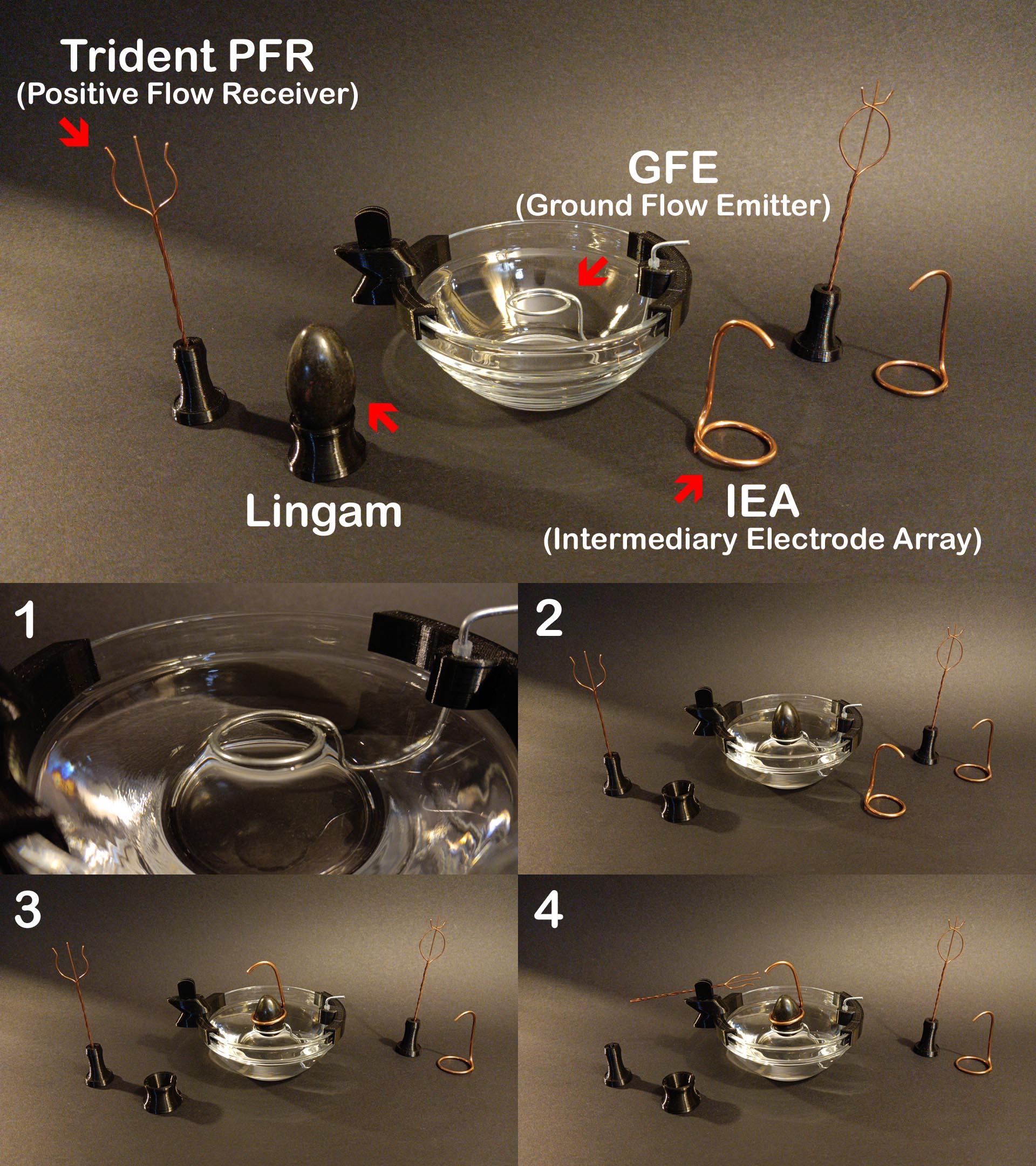
1) Fill up the water reservoir until water is only touching the lower GFE ring level.
2) Place your lingam stone securely onto the GFE ring (rotate until there is a fit) and recheck that water is only touching the lower part of the GFE and not at or above the ring's top level.
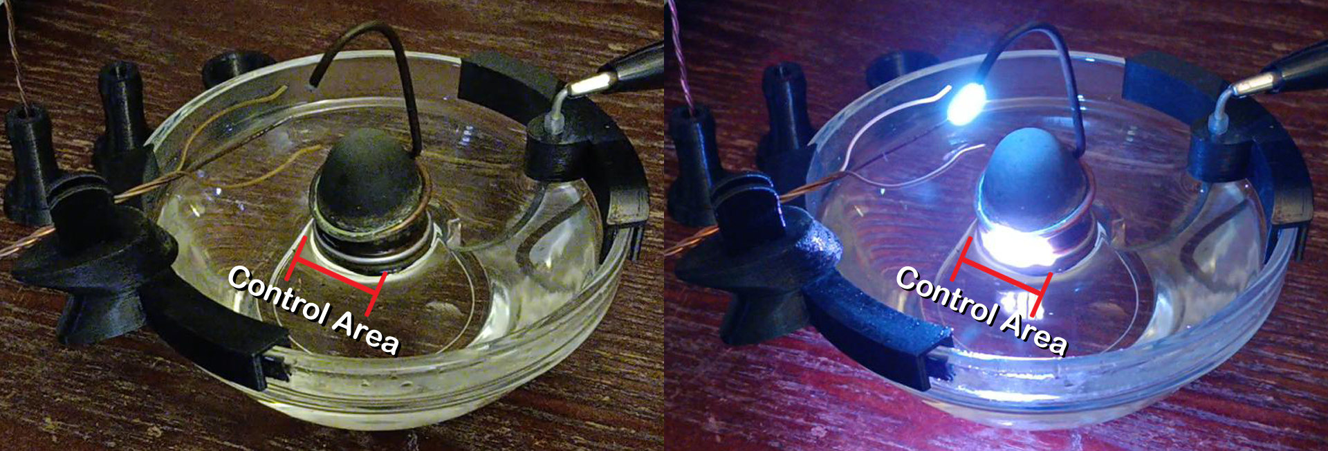
3) Position the Intermediary Electrode Array onto the lingam stone, making sure to both distance and tilt it at high enough of an angle so that sparks emitted are contained in a projected control area on the corresponding GFE ring (usually away from the rear ground wire). Be certain that the rear of the IEA is also angled at a high enough distance away from the rear GFE's bottom ring than at your desired control area, or it can spark at this unfavorable location. The ideal distance between the IEA and your projected control area is approximately 3.5 - 6 millimeters for an SGL at this size and scale.
SETUP / ADJUSTMENT
4) Once the lingam and IEA have been preliminarily adjusted, the Trident PFR can lastly be added into the system by positioning it securely in its holder and pointing the middle tip towards the tip of the IEA. There are several configurations available here, as the distance from, angle and position to the PFR will also control voltage flow throughout the entire system - this distance can be anywhere from about 4 - 6 millimeters for your SGL's size and scale. The PFR holder is movable and can rotate left and right; use this feature to help align your electrodes.
*BEFORE MAKING ANY ADJUSTMENTS, always ground out or disconnect your capacitors. DO NOT TOUCH THE ELECTRODES without first TURNING OFF POWER and making sure your capacitors and connected systems are SAFE. The extreme voltage levels we are working with here are incredibly dangerous and must ALWAYS be respected. One mistake can be your last if not continually attentive. Work wisely. Work safely.
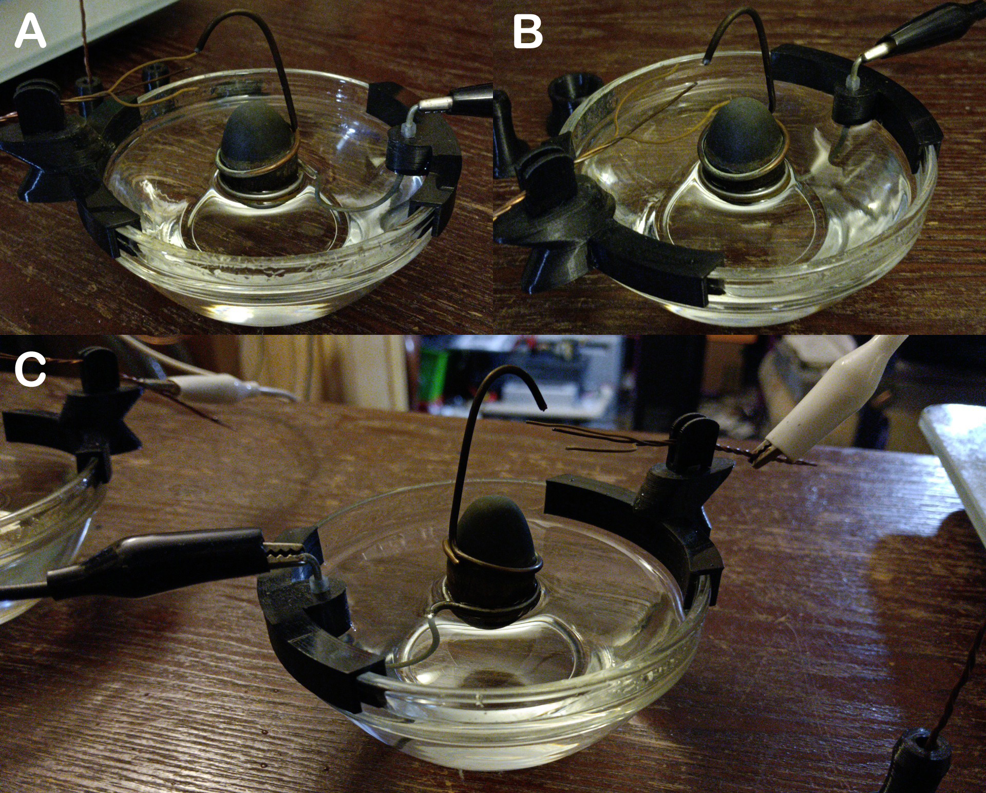
A properly configured SGL will resemble the one in the above pictures, considering each rule of Trident angle, IEA tilt and electrode distances have all been followed.
5) Power on the system briefly. The first few firings of an SGL right after setting up a fresh system will usually quickly ground out until either there is enough water between the lingam stone and lower GFE ring (water must both saturate this location and move slightly up the lingam walls before it will run reliably); an effect of which is naturally attained by current moving throughout the system while it's running, and why a fresh setup must more-than-likely be pre-fired or even adjusted possibly several times.
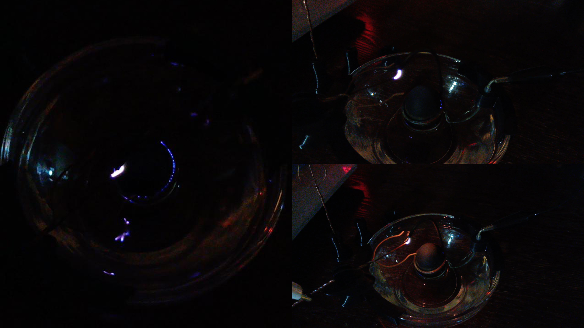
You can see some of the more common setup failures in the pictures below, caused by either improper water levels, electrode misalignment or too much amperage being applied. The first few firings of a freshly setup lingam may resemble these illustrated failures, however do not get discouraged, and do not allow the electrodes to burn for any longer than is required to restart.
RUNNING THE SGL SYSTEM
Always adjust and double-check every wire and electrode alignment before applying power!
DO NOT TOUCH THE ELECTRODES without first turning off the power and disconnecting or grounding out your capacitors. "Capacitor shock" is both dangerous and unhealthy.

Once power is applied, a distinctive roar or 'banshee scream' will be heard when the system is pulling water and voltage properly. With practice, you will become very familiar with this sound and how it correlates to the voltage and amperage flowing, and you can also eventually use this tone to gauge how the system is performing at several deeper levels.
TROUBLESHOOTING / TIPS
No spark - increase your voltage or shorten the distances between spark gaps.
Tip: If you temporarily push the IEA's tip closer to the Trident's, this should simultaneously shorten the distance between all electrodes and allow you to prime the system quicker.
Electrodes catching fire - This can either be caused by insufficient capacitance, too much voltage / amperage, a low water level, too high a water level, or your electrodes may be too close together. Check over the system carefully and make sure it is within specifications, then try turning down the voltage / amperage first before adding more capacitance.
Tip: If the water level is below the GFE ring or too high around or above it, this can also cause shorting from over-heating or water splashing on / grounding out the sparks charges through the stone instead.
Control area / GFE ring issues - If the spark fails to consistently remain within the control area or continually converges into one single arc, first check the angle of the IEA; too steep or too shallow an angle can cause this symptom, however, there may also be contamination build-up or dammage, such as corrosion or a burr on either or both of the IEA and GFE's rings.
Tip: If undesired operation arises from control area issues even after careful adjustment, remove and dry off the GFE, then lightly sand (using a fine grit paper) the GFE or IEA's rings on the entire working surface.
CARING FOR / MAINTENANCE OF YOUR SGL
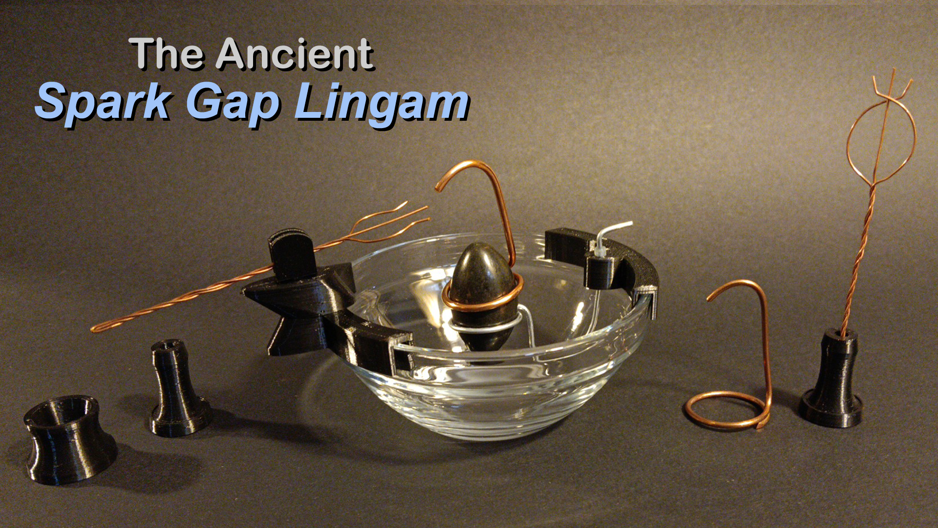
An SGL is delicate scientific equipment. Especially at this miniature introductory scale, always use care when handling, setting up, adjusting and operating this ancient, advanced spark gap.
Most lingam stones you find for purchase anywhere will arrive with a light coating of wax. During the first few runs of a new stone, if wax is present, it will quickly melt and cloud up the water reservoir. If this occurs, simply drain and refill the reservoir with fresh water, then run your SGL for a few more cycles, repeating this process until the excess wax has cleared.
Always empty all water from the reservoir when not in use then clean and dry off all electrodes, otherwise corrosion can quickly form which will affect the reliability of the system.
Never keep the electrodes exposed to water for extended periods of time, such as allowing the SGL to sit out wet overnight. The parts will wear with use and time, however replacements such as the entire GFE ring assembly can be found in the 'Science Store' section of my website.
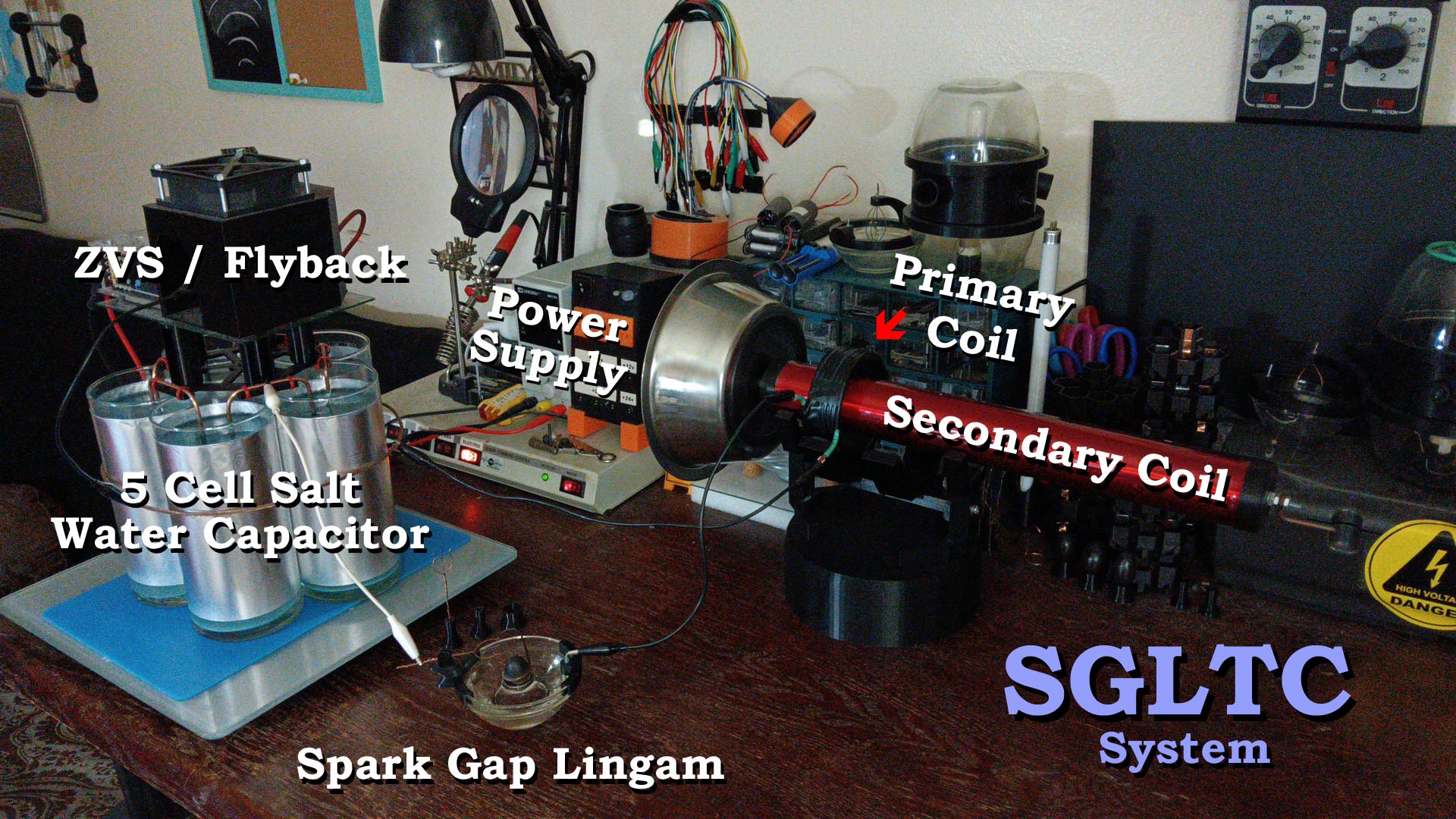
INTEGRATING YOUR SGL INTO AN 'SGLTC' SYSTEM
The power of your SGL can be harnessed in many ways, one of which is when integrated into a Tesla coil system. An 'SGLTC', or 'Spark Gap Lingam Tesla Coil' is in fact a new type of Tesla coil, one you now have an exclusive ability to explore. The following pictures are a quick overview of setting up your first SGLTC - then when you're ready to graduate, you might even try a 'Double Primary Spark Gap Lingam Tesla Coil', or the 'DPSGLTC' for short... Happy experimenting!!