February 15th, 2025
John Bidwell
An introduction to the future of advanced capacitor charging systems...
From my latest discovery 'Electro-tesla-mechanics' comes yet another interesting physical use for high-amperage water-cooled spark gaps; charging extremely large capacitor systems to millions and billions of volts (depending on size of capacitors and coils used, Fig. 1) and then keeping them pumped to perform a myriad of physical, electro-mechanical, electro-tesla-mechanical and MANY other general, light to heavy electrical applications.
INTRODUCTION
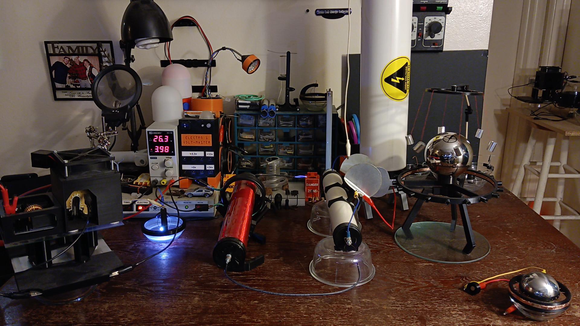
Wirelessly charging a capacitor is incredibly important because in this 'wireless / separated' state, you are able to effectively harness the power of a water-cooled spark gap tesla-coil (WCSGTC, Fig. 2) to charge without back flux (unlike with wires) and keep charged while under load, massive capacitor systems that before had required complex, bulky or expensive machinery to perform these similar tasks; except now, capacitors are also viably able to reach unfathomable voltages never thought possible - they are now capable of running large machinery AND performing HEAVY PHYSICAL LABOR, unlike ANY capacitance system before...
MATERIALS AND METHODS
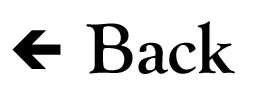
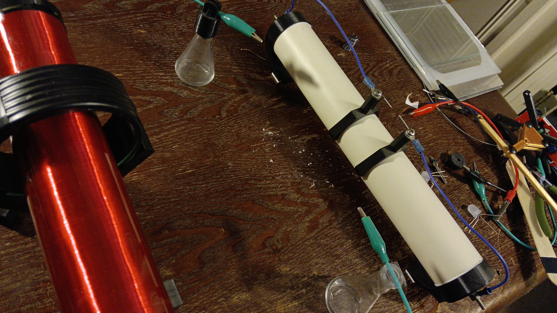
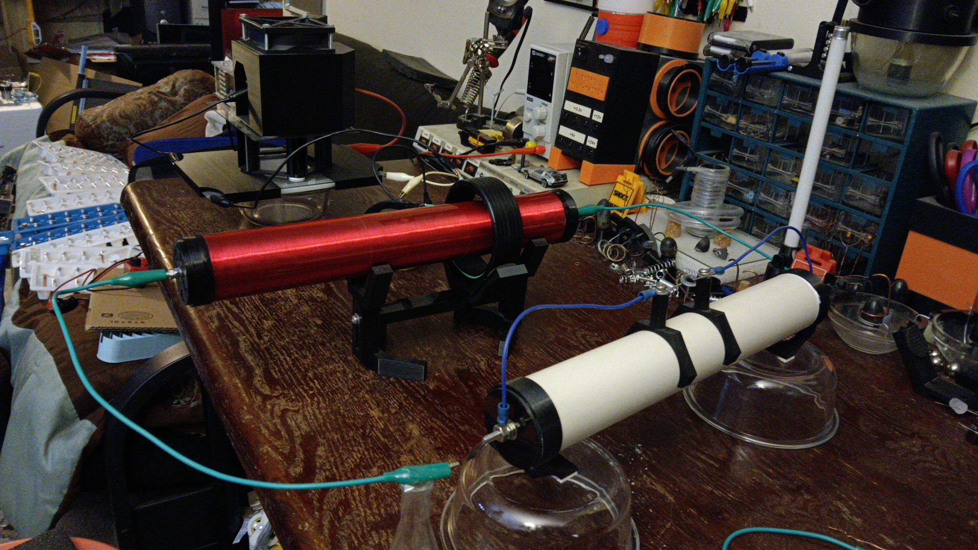
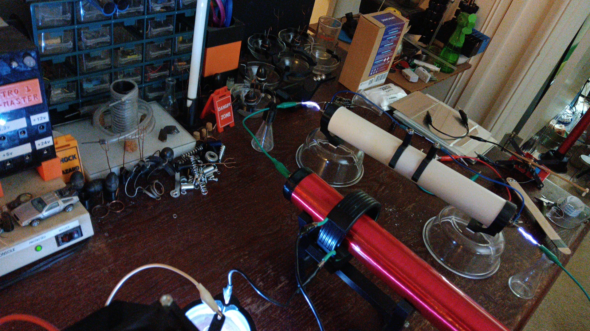
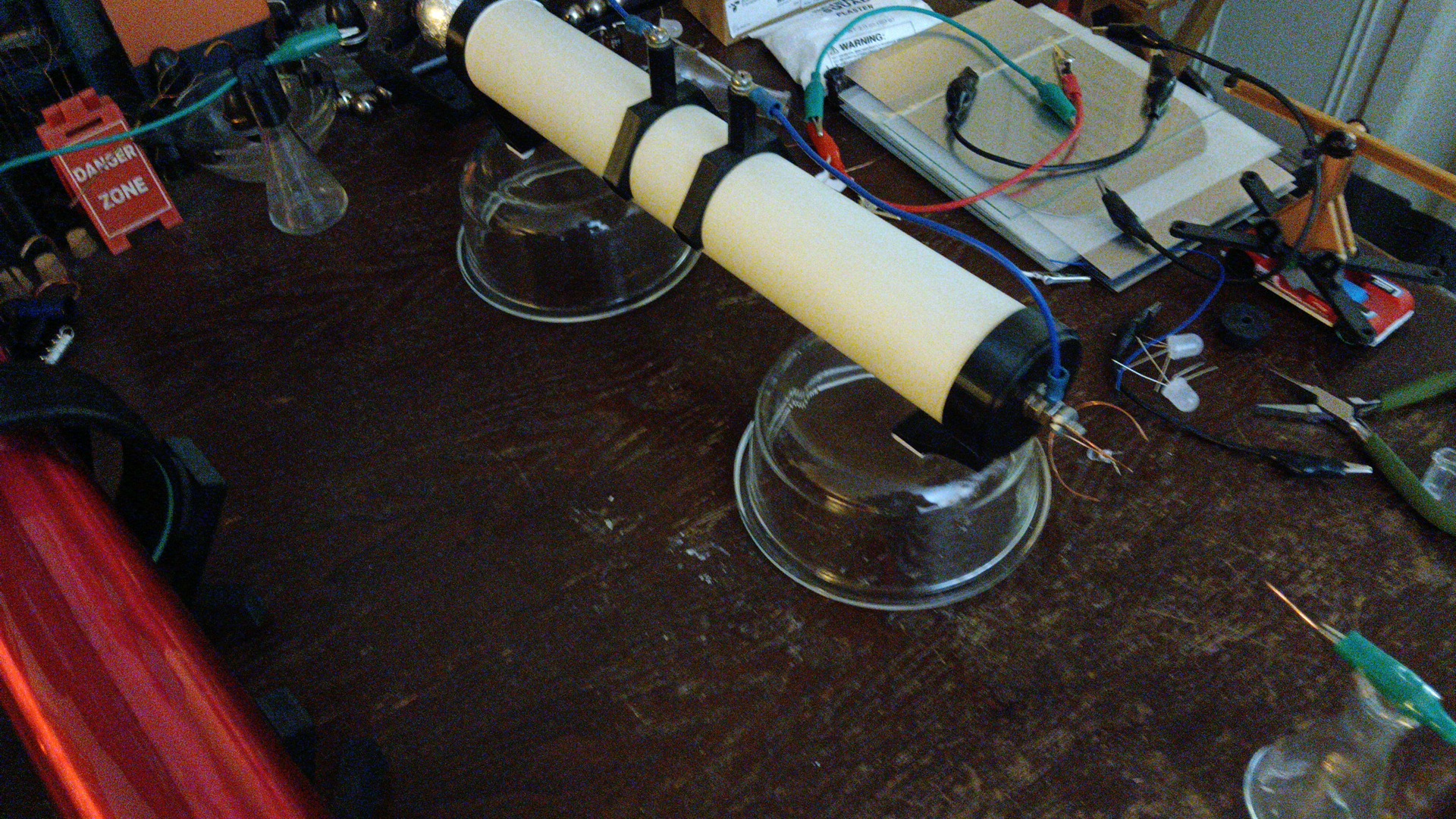
The over-all basic system is comprised of a bi-pole WCSGTC setup (Fig. 3), a primary run capacitor or bank of caps capable of taking at least 500,000 to 1,000,000 volts (Fig. 4, this is the very minimum entry-level coil size and capacitance for a small-scale desktop WCS system), a plasma flow receiver (Fig. 5) and to draw or tap off of the larger capacitors power, an additional 'voltage flow limiter' (Fig. 6), HV / LV Splitter (Fig. 7) and a secondary, smaller capacitor bank (electronic size, such as 200uf and above, Fig. 8) for storage and smoothing that can be then tapped for lighting or other non-sensitive electronic applications (as electro-tesla-mechanical 'pull' is still present in the back-end of the system; this high-frequency / high-amperage 'noise' must first be smoothed with an HF filter so that sensitive electronics may also then be attached and run off the 'live', engaged system - or else they will need to be disconnected until primary capacitor charging is complete).
System Component Overview
Overview 1 (Fig. 10), Overview 2 (Fig. 11)
1) WCSGTC or a similar high-amperage tesla coil setup.
2) Flow Emitter - usually consists of ONE single tip as the top-load of a tesla coil, but this tip can have multiple points of plasma discharge for larger scale applications.
3) Flow Receiver - consists of multiple conductive points / tips connected to the capacitors positive side.
4) Primary / Positive Plasma Gap - controls, disperses and connects a positive plasma flow onto the capacitors 'Flow Receiver'.
5) Secondary / Negative Plasma 'Pull' Gap - regulates system voltage flow and strength of Electro-tesla-mechanical 'pull' exerted on the Positive Plasma Gap.
6) Primary run and smoothing capacitors - needed to absorb, smooth, control and collect some of the still-fluxuating (AC) charges emitted from the system's tesla coil.
7) Overload spark gap - *this is an important but optional, adjustable feature to prevent potential-overload backfires (green plasma discharges) and to keep your caps safe from internal overload shorting.
8) HV Flow Limiter - allows high-potential electro-magnetic energy transfer through many points which dissipate charge through the lower side of the system, all without A SINGLE SPARK that would of course short, destroy components and reset the capcitor's voltage back to zero.
HV / LV Splitter
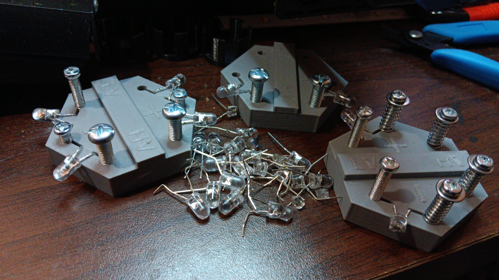
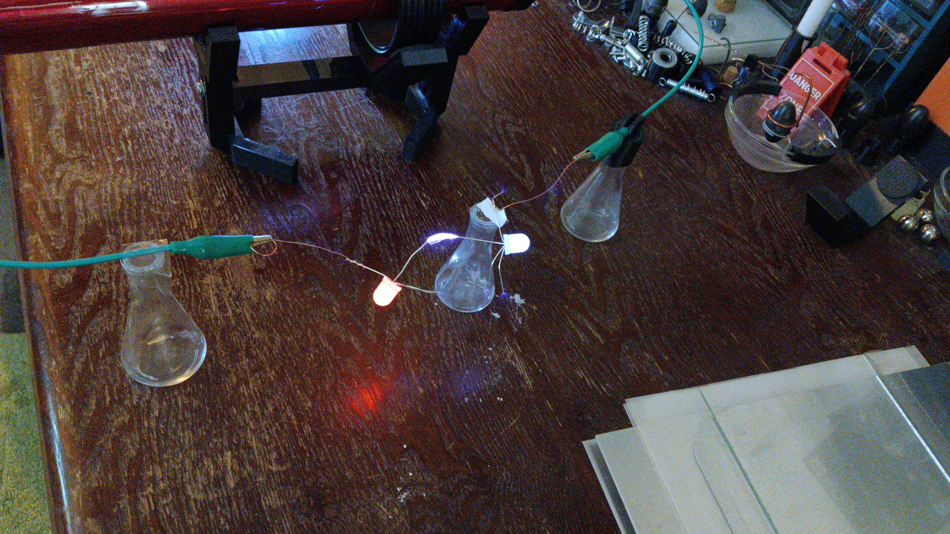
The High-voltage / Low-voltage splitter (Fig. 12) takes the still-fluxuating (but mostly positive) voltage passed through the 'HV Flow Limiter' and also the mostly-negative fluxuating input line directly from the primary capacitor, then routes them separately to the low-voltage side of the system via an identical (polarity respected) set of heavy inductors and 2.2v LED pairs. This pairing smooths flow and keeps start-up or sudden voltage discharge spikes from popping LED's or damaging equipment and other components attached to the low-voltage output side of the system.

HIGH VOLTAGE SIDE
9) Induction smoothing / flux back control - without these heavy smoothing inductors, the LED diodes will overload and pop (also damaging connected low-voltage equipment) under several conditions such as system start-up, primary capacitor overload or any other situation involving sudden discharges or high voltage spikes. This is the first step of connected LV component circuit protection.
10) LED diodes - *These are very important to use as the superconductor material both directs, controls and limits current, and then regulates the overall flow by also releasing excess energy as light. THE ACTIVATION VOLTAGE OF THE LED DIODE (2.2 volt LED's are used in this demonstration system) IS WHAT IS PASSED THROUGH TO THE LOWER SIDE OF THE SYSTEM and when also used as part of the 'load', they SET / REGULATE THE MAXIMUM VOLTAGE THE 'LV' SIDE CAPS WILL CHARGE UP TO... This is also the second step of circuit protection via system monitoring (the HV / LV Splitter LED's will pop like a visual fuse to notify of failure, i.e. they don't shine solid anymore and become dim or flicker sporadically instead of smooth).
LOW VOLTAGE SIDE
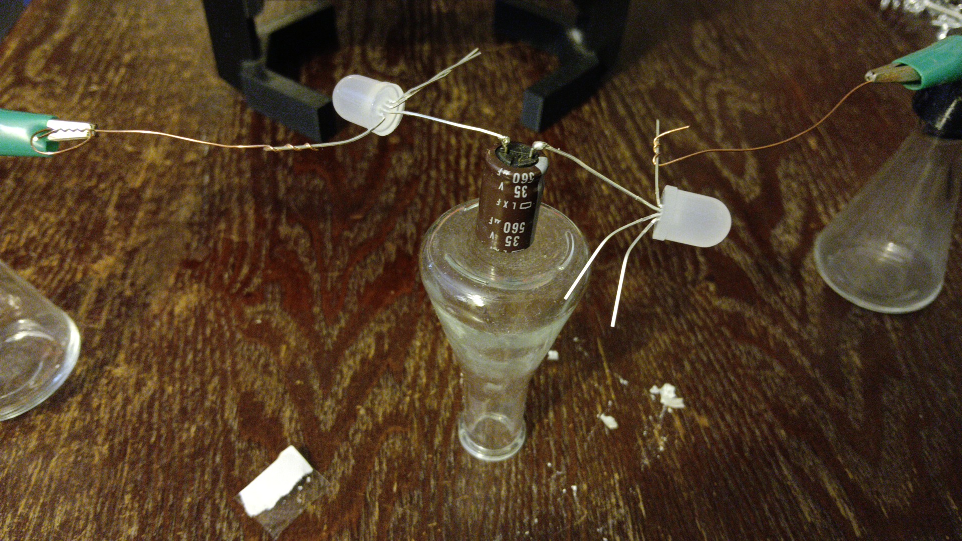
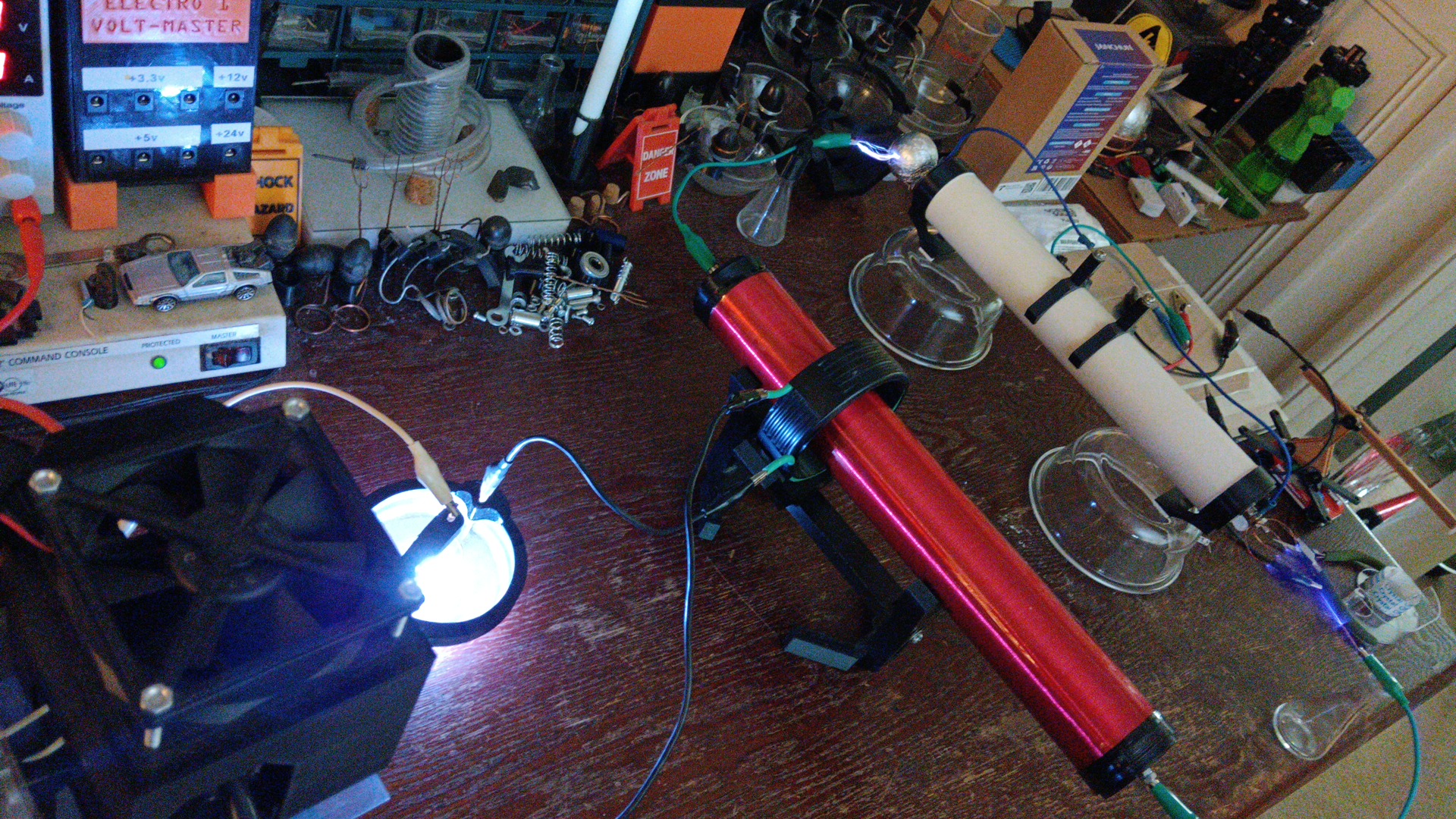
The low voltage side goes directly to a secondary capacitor bank (Fig. 13) - it can be tapped for 'live' loads while the tesla-coil is active (Fig. 14), such as for lighting and other non-IC, non-sensitive electrical applications, however, the tesla-coil will have to be disengaged before connecting power to more sensitive components on the LOW VOLTAGE SIDE's capacitor bank unless further voltage smoothing is applied.
POSITIVE PLASMA GAP AND FLOW RECEIVER ADJUSTMENTS
The positive flow receiver on the primary run capacitors can be adjusted away or towards the flow emitter (and via a mechanical system during LIVE operations) to control and regulate the primary run capacitor output, however fully aligned and properly engaged electrodes (Fig. 15) will transfer the most power through the Positive Plasma Gap (Fig. 16).
NEGATIVE PLASMA 'PULL' GAP AND 'PULL TAIL' ADJUSTMENTS
The Negative Plasma 'Pull' Gap consists of a simple wire returning to the low / negative side of the tesla-coil, air-gapped to the primary RUN capacitors 'Pull tail' assembly (Fig. 17). This gap should not be too close as it will hinder a good 'pull' of electro-magnetic waves, and being too far apart of course will also weaken the electro-tesla-mechanical 'pull' required for strong / effective capacitor charging.
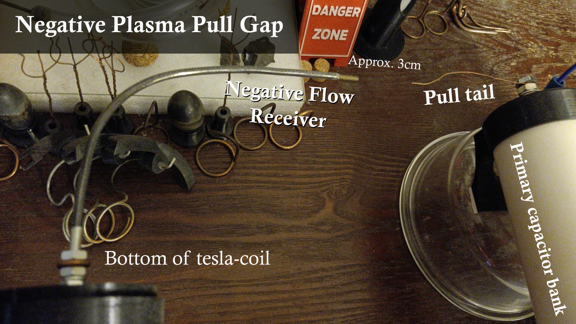
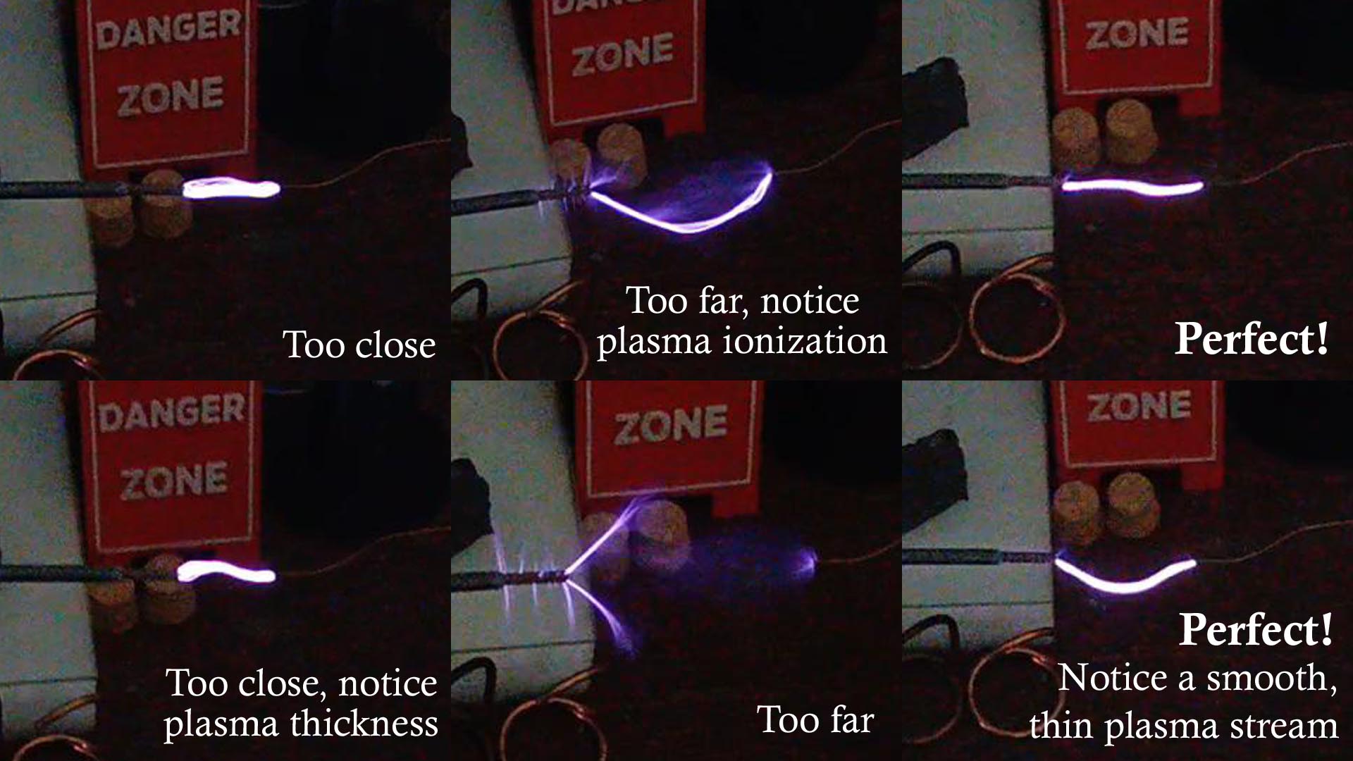
Ideal distance and position between the Negative Flow Receiver and 'Pull tail' of the negative plasma gap should reflect upon a pre-measured point at about 75% or three-fourths of the plasma stream's MAXIMUM TRAVEL DISTANCE (stretch before the solid negative plasma stream breaks, Fig. 18) as this will be the strongest (amperage) flow point and position for nominal system performance, i.e. quickly charging and keeping the primary run capacitor bank pumped with charge.
This negative plasma gap shouldn't need any further adjustment other than finding its 3/4ths point described previously above, however it too can have a future mechanical mechanism put in place to make finer adjustments or counter-react to different loads during LIVE OPERATION (such as the 3/4ths distance may change with less or more load on the tesla-coil and system, or by increasing / decreasing WCSGTC output).
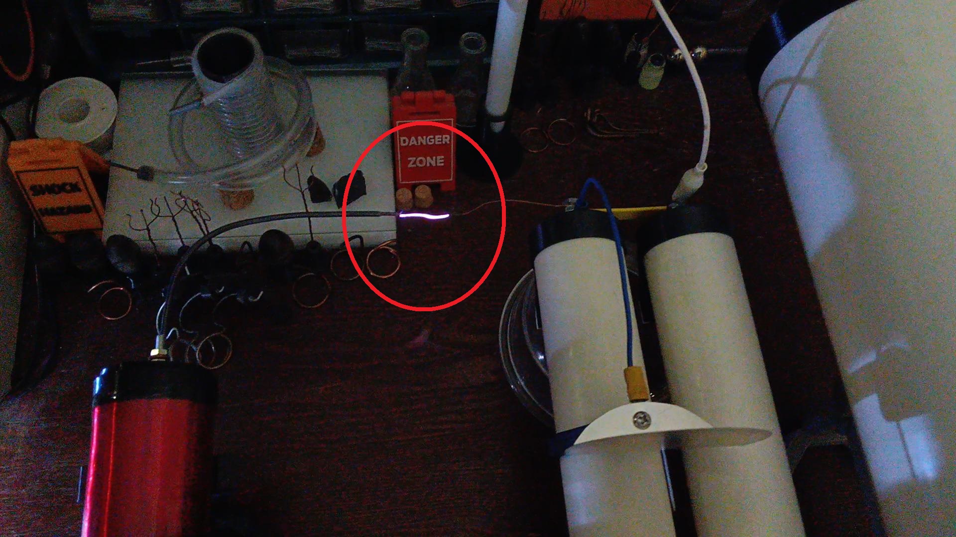
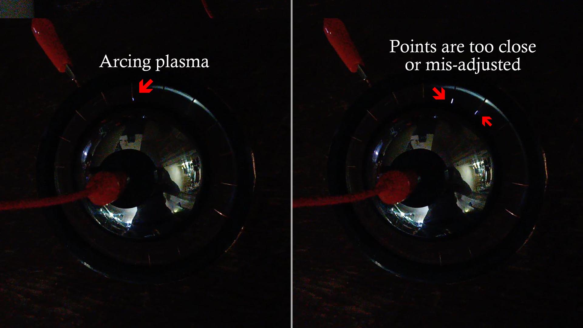
Below are some visual queue's to help with identifying different plasma streams and properly setting up the negative plasma 'pull' gap (Fig. 19).
HV FLOW LIMITER
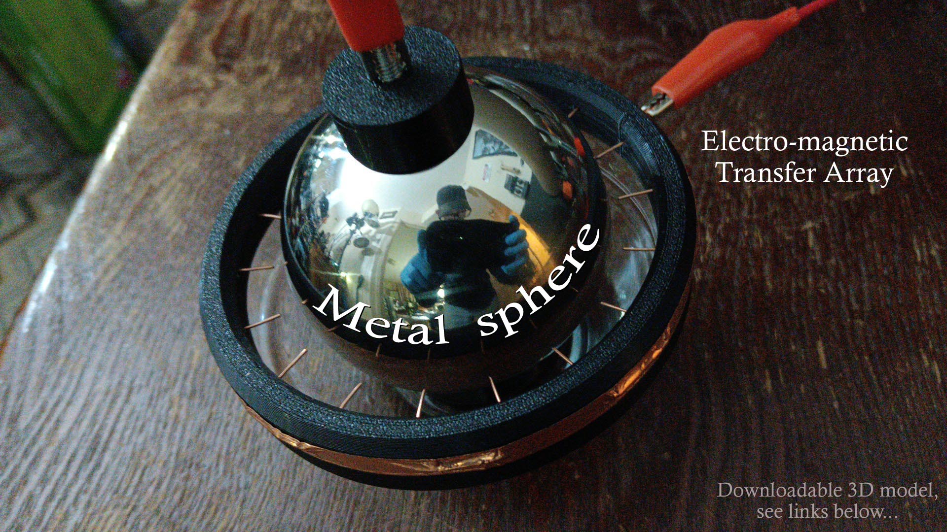
An HV Flow Limiter (Fig. 20) is a device that limits the main run capacitor's full high-potential flow from discharging suddenly (preventing any and all sparks that would otherwise instantly ground out the entire capacitor bank) by weakly dissipating very high-potential electro-magnetic waves from the sphere and then absorbing them at many points around an electro-magnetic transfer array, with either the sphere or these multiple points being set closer or farther apart from each other to limit and regulate voltage.
The HV Flow Limiter is comprised of a few basic parts (the 3D printable ring and other models shown in this journal are available for download and include build instructions). These are very specialized parts essential in effective electro-magnetic wave transfer.
HV FLOW LIMITER PARTS:
Metal sphere - a smooth, whole (complete) metal sphere is usually required as it helps contain the electro-magnetic waves to the evenly rounded surface and does not allow escape or build-up of dangerous potential on any uneven or oblong areas, especially shapes with points or surface defects like welds or electrode attachment points.
Insulated base - (Fig. 21) an insulated base that not only separates the metal sphere from the surrounding environment (a table or workspace) but holds the sphere securely in position during operation. None of these parts or materials used here can be conductive in any way as this directly connects to the high-potential side of the primary capacitor and during live operation (tesla-coil active), some plasma discharges may also occur.
Electro-magnetic Transfer Array - (Fig. 22) this structure holds an array of COPPER wire points (copper should be used here in this specific assembly because it does not collect / saturate with electro-magnetic waves like steel or other conductive metals which is a characteristic that helps prevent potential sparks) and can be situated in a ring or any other concentric, even formation around the sphere (once again not to disturb the balance of electro-magnetic waves on the sphere's surface which can result in a spark or failure).
High-potential Lead-in - this line goes directly to (the top or bottom of) the sphere from the primary capacitor bank positive.
Regulated lead-out - this goes to the HV / LV splitter or regulated, lower-voltage end of the system.
Magnetic connector - (Fig. 23) Recommended because if there are any burs or misshapes on the sphere (from welds / connection points), they will create potential static build-up zones that promote / can cause discharges, so a magnetic connector should be used since the small disc-magnet pulls flat onto the sphere's rounded surface, provides very smooth electro-magnetic wave transfers and is also a very simple yet versatile mounting option.
SETUP AND ALIGNMENT
This feature has 3 key factors that need to be considered based on the power and scale of the Wireless Capacitor System which voltage is being applied from.
1) The primary capacitor's fully charged, maximum discharge arc.
2) Distance between the Electro-magnetic Transfer Array absorption points and the metal sphere.
3) The number of absorption points being used or engaged.
The distance needed to be set between the copper wire points and metal sphere should be roughly about 1/4th (one fourth) the distance of the primary capacitor's maximum discharge arc length - for example, if when fully charged and the primary capacitor's maximum discharge arc is 1 centimeter; then the distance between all copper points and the metal sphere should be about 1/4 centimeter (0.25 cm) and EVENLY SPACED both from each other (copper point to adjoining copper point) while also keeping an equal distance from the sphere.
A properly setup and aligned Flow Limiter will resemble the one in the image below (Fig. 24), note the concentric alignment of all the parts as a whole - this is crucial for even electro-magnetic wave interactions and transfers.
It is CRUCIAL to carefully and precisely setup the entire HV Flow Limiter unit because if one single arc discharges from the high-potential side of the main run capacitor for any reason (Fig. 25), it will then dump the entire load into the LV / HV splitter; destroying voltage regulator diodes and possibly damaging some or all attached components that are on the low-voltage side / secondary capacitor bank.
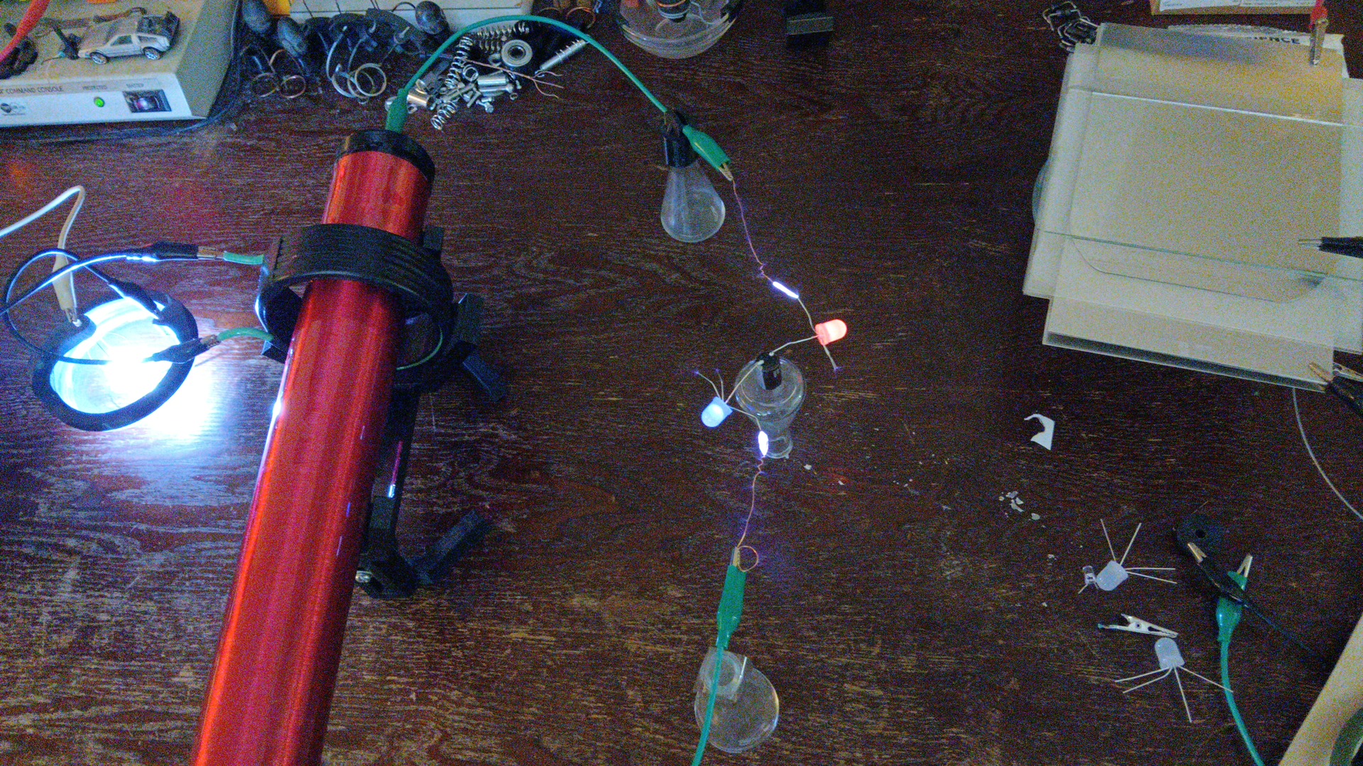
In the still series of images shown below from 'Part 2' of my world-first Wireless Capacitor YouTube video, you can see a bit of what a huge capacitor's potential (one that has been mostly drained or the white regulator LED's shown which did break, would have instead popped to pieces) suddenly being dumped into the HV / LV Splitter and low-voltage side when I purposefully short the metal sphere to its copper wire absorption points for demonstration.
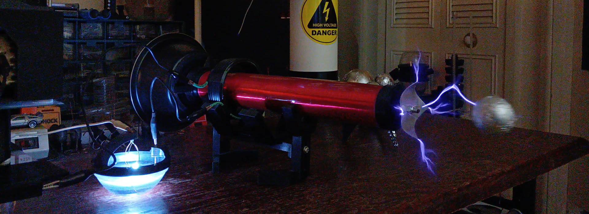
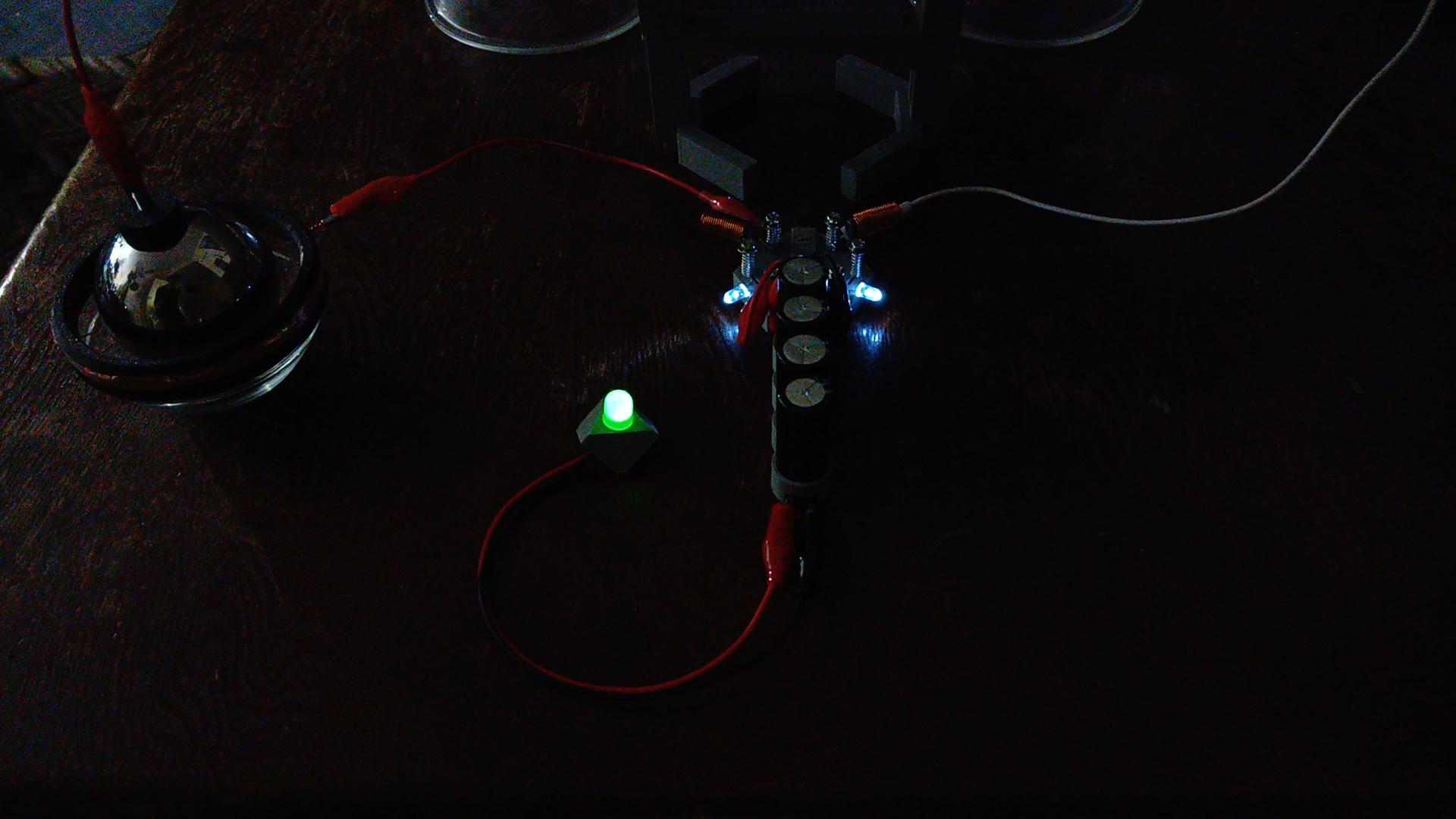
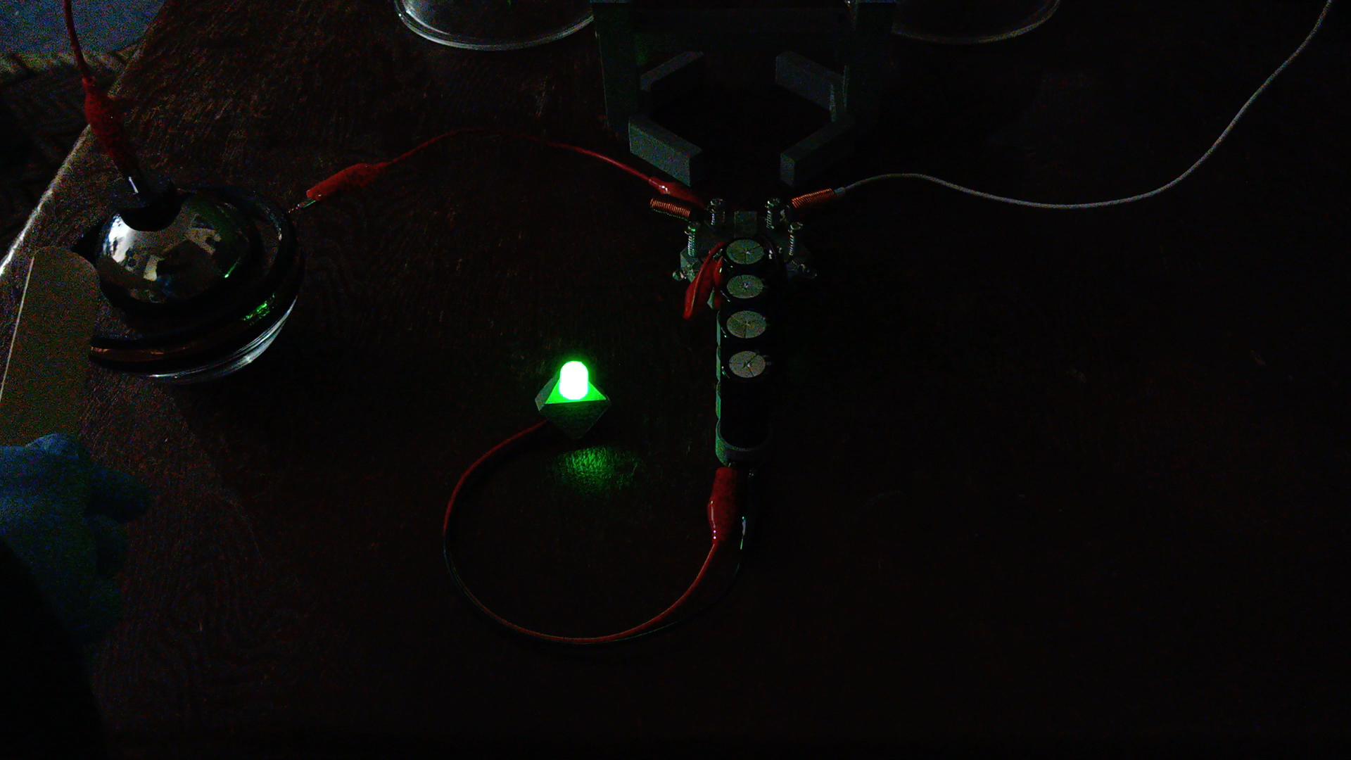
Here is a smoothly-tuned active HV Flow Limiter, perfectly powering the lower-voltage secondary capacitor bank and a green LED example load (Fig. 26).
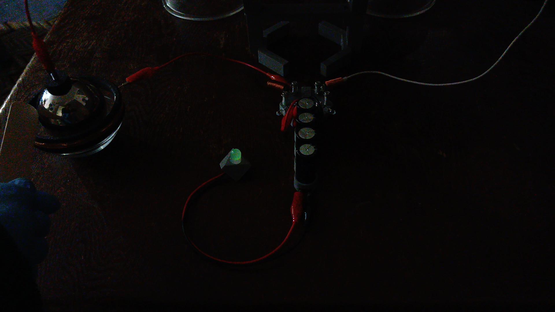
Moments before purposefully causing a catastrophic short for demonstration (Fig. 27). You NEVER EVER want a spark or discharge anywhere in or near the Flow Limiter unit as THINGS WILL BREAK, i.e. if the primary capacitor's raw unmetered discharge can make the component pop (it probably can), then a short anywhere in the HV Limiter WILL POP IT AND ALL COMPONENTS OF THE LOW-VOLTAGE SIDE IT TRAVELS THROUGH...
Here you can see the massive influx of power as all remaining energy from the primary capacitor bank (which was only briefly on, being used and mostly drained telling by the white regulator LED's lit / faded status) as it rips through the lower-voltage side of the system (Fig. 28), instantly destroying the white regulator LED's and giving both the secondary caps and green LED example load quite a jolt of juice.
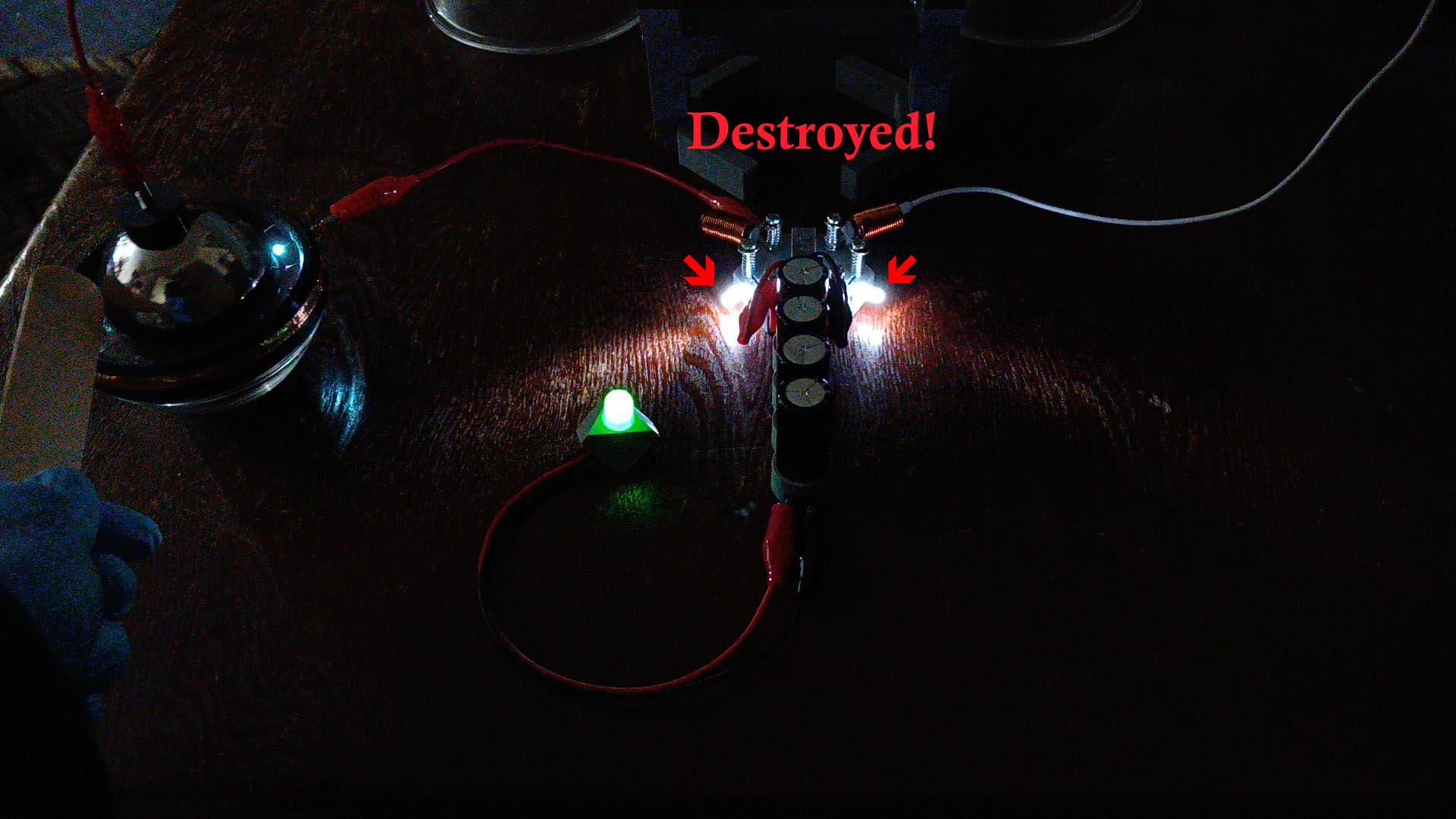
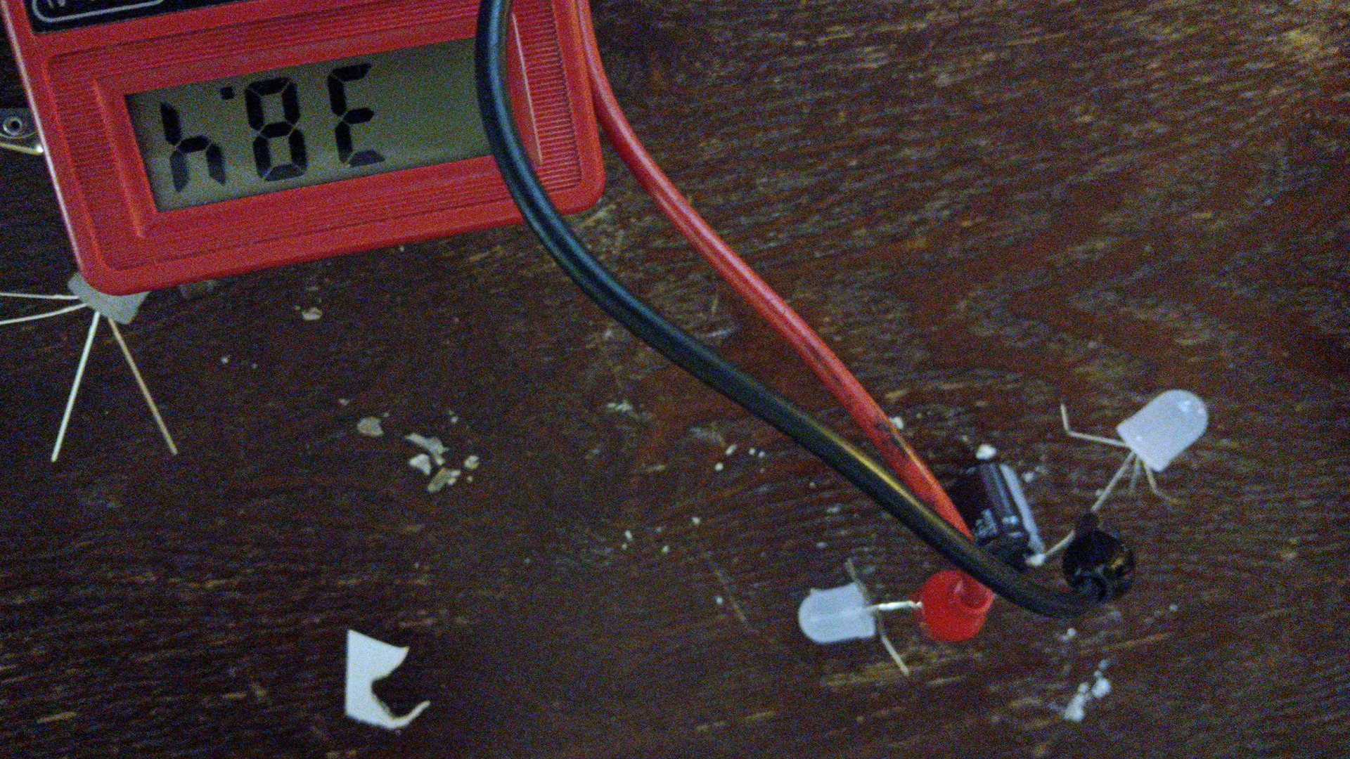
Secondary capacitors and attached loads also receive a good portion of the primary capacitors dumped voltage and can / will be damaged (Fig. 29) in the event of a Flow Limiter failure. Special surge protection units must soon be designed and put into place for later consumer and production items (i.e. tools, appliances, electronics and ANYTHING ELSE THAT CAN BE POWERED!) so this is one area in which entirely needs you, the experimenters, for further development!
Keep the importance and fine function of the Flow Limiter utmost in mind when you get to this chapter in setting up your system, and especially when attaching components to the low-voltage side (don't forget about also handling residual electro-tesla-mechanical force for fine or delicate circuits described next) because this will save you a lot of broken voltage regulator LED's and test components; as you can see from just some of the nearly 100 LED's alone I've gone through in the course of discovering, testing, understanding, and creating all of the methods and hardware shown while writing this science journal...
PRESENCE OF ELECTRO-TESLA-MECHANICAL FORCE
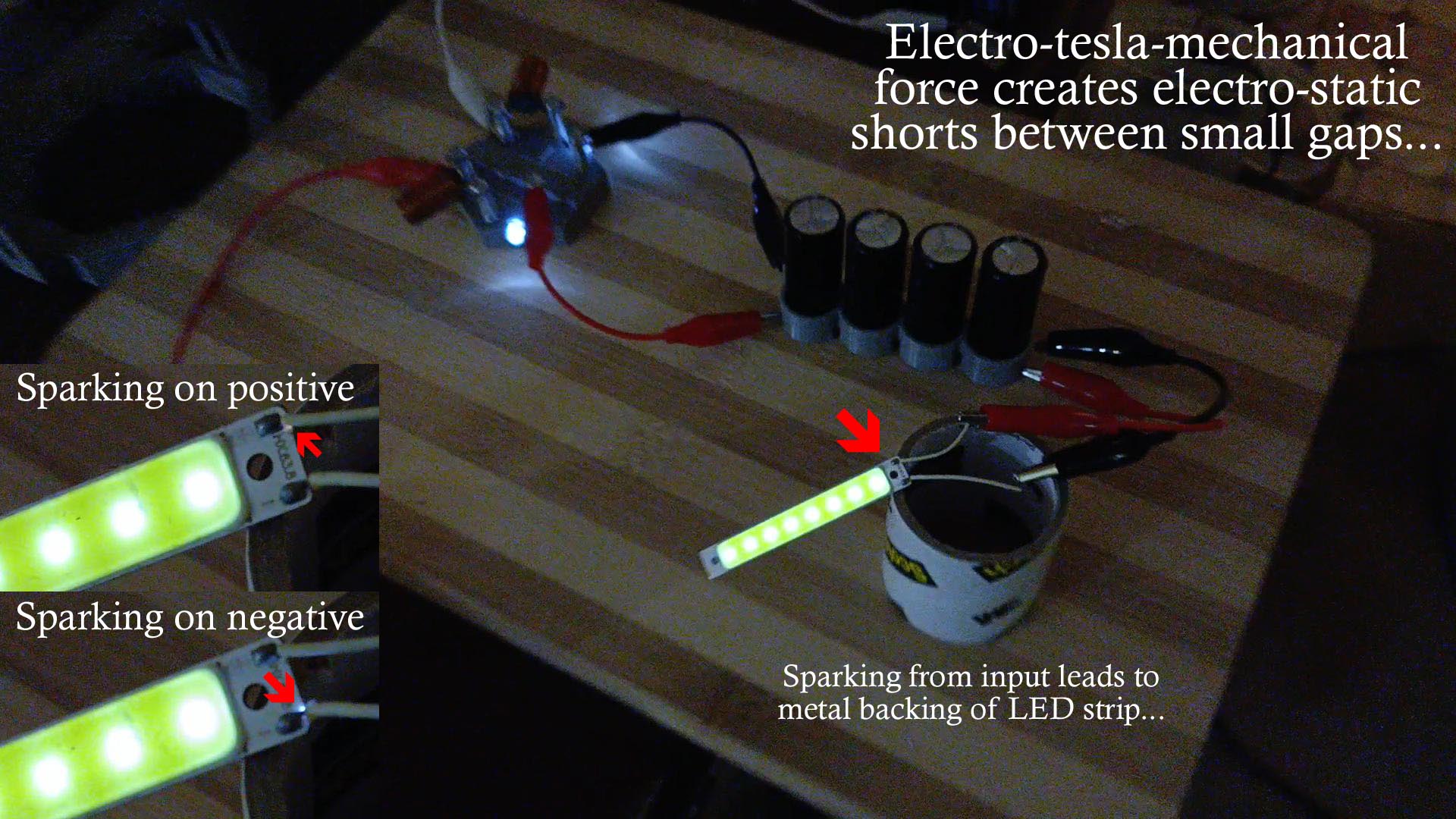
Because electro-tesla-mechanical force and 'pull' is present from being connected directly to the negative side of the primary run capacitors, electro-static potential build-up occurs (Fig. 31) that will arc and ground out over small gaps about 1mm or less, rendering sensitive circuits like IC's useless until a filter is put into place (Fig. 32) that can collect and dissipate this charge build-up.
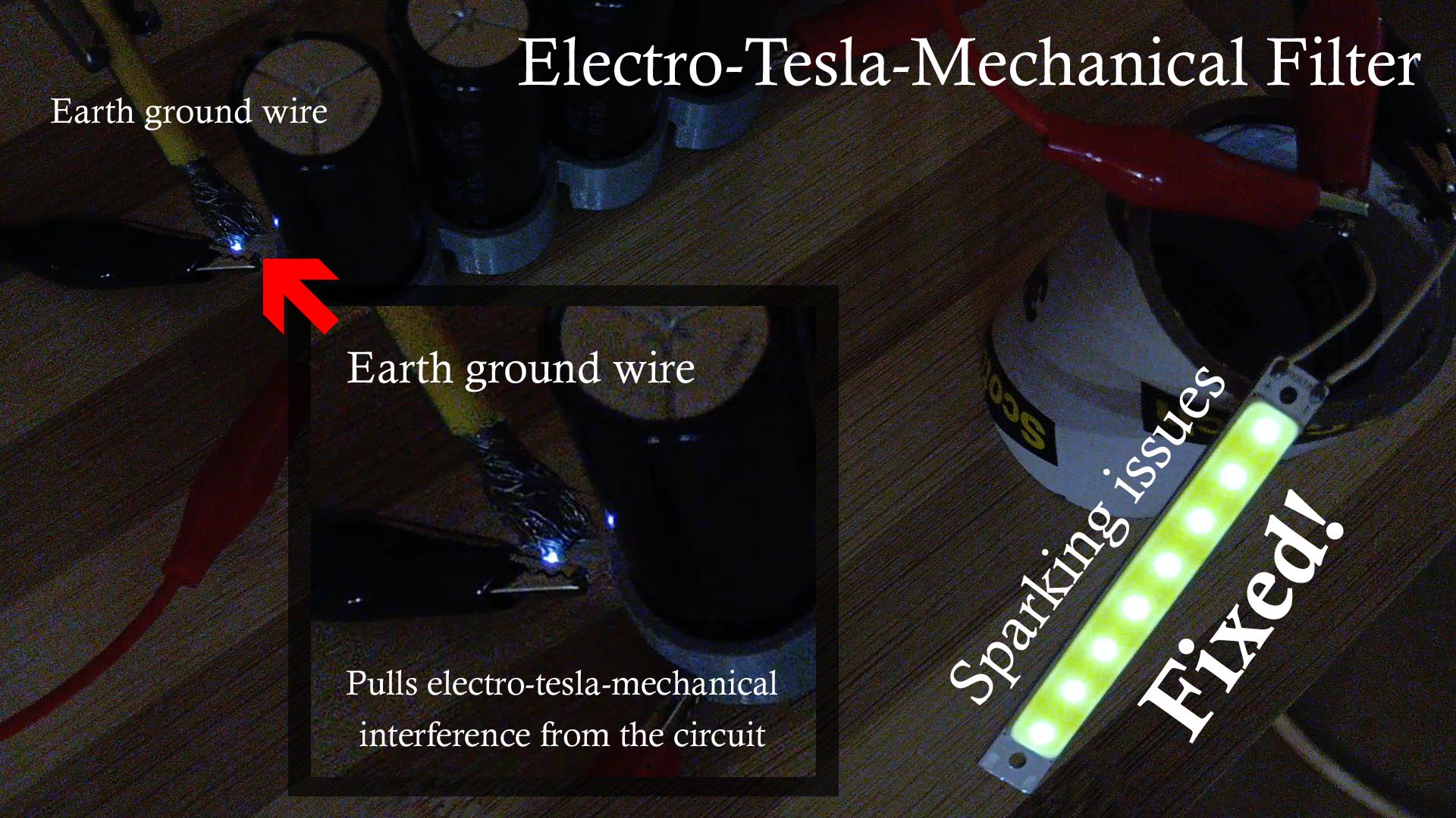
ELECTRO-TESLA-MECHANICAL FILTER
A simple filter can be applied with pulling the majority of this force off of the system by placing a separate earth ground wire about 1 mm from the secondary capacitor bank's negative input, however, this will create a DRAW OF HIGH AMPERAGE that will destroy lower-rated diodes (such as the LED voltage regulators used in the HV / LV Splitter, Fig. 32), so higher-rated diodes will need to be placed at this part of the circuit to both either perform higher-rated current draw or to have an 'earth ground wire' electro-tesla-mechanical filter installed like this one (notice I do not have this feature in the production / video versions because of breaking so many diodes and also to keep the visual LED feedback of the system).
RESULTS
By harnessing the electro-tesla-mechanical 'pull' of high-amperage water-cooled spark gap tesla coils (WCSGTC's), incredibly massive capacitor systems can now be built and charged to historic new heights, as quite simply, a tesla-coil's over-all output will always outmatch that of any other device on both scale and simplicity - except before, you couldn't charge a capacitor with plasma - and by understanding this simple fact, that a capacitor can now be powered by HIGH-AMPERAGE PLASMA DIRECTLY (and much more such as LEDs plus other electrical lighting or appliances) - it will then allow you to begin to postulate the future importance, growth and necessity of such technologies which will NO DOUBT EASILY and EFFICTIVELY power newer devices designed to run on an efficient, massive capacitance system (charging only when needed or in use), or be powered from pure, high-amperage plasma alone...
HINT: This extremely high-energy green plasma discharge (Fig. 33) should also be immediately explored - for plasma isn't ever usually GREEN except when exciting different gases (not plain air) or when inside of a vacuum... Use great caution, as this is an EXTREMELY POWERFUL DISCHARGE that POPS AND SOUNDS LIKE A SPARK and also FLUCTUATES THIS ENERGY THROUGHOUT THE TESLA COIL! Can you begin to imagine then, for instance, a new kind of spark gap using that kind of a discharge PER SPARK will open the doors (again) to incredible new high-voltage plateaus - volt on!!

NOTES:
1) Wires should be kept short on all parts of the system (because they will also act as 'electro-magnetic wave antennas', becoming charged by electro-magnetic radiation when the tesla-coil is active not from just the coil but the entire system - including from the primary capacitor bank), and ideally the LOW VOLTAGE SIDE should be routed far from the tesla-coil and capacitor systems as strong electro-tesla-mechanical 'pull' is present closer to the Negative Plasma Gap that can arc to sensitive components such as IC's - until an HV filter can later be added that adequately handles this 'pull'.
2) Using thinner gauge wires on the low voltage side (18 gauge), particularly the one direct from the primary capacitor bank itself to the positive HV / LV Splitter, will also assist in limiting and controlling voltage flow.
3) LED's are quite important to use (at least for now / preliminary studies) because their superconductor material both limits voltage flow and burns off excess energy as light, which is an excellent side-effect / indication of many things such as system performance, output voltage / stability and primarily, if your voltage control diodes are still intact and light smoothand light smooth (wild flickering from arcs across a broken or missing diode means the low-voltage side will then have very high, un-metered voltage that can damage small capacitors and components). I have actually found LED's to be quite amazing little delights whilst exploring plasma and high-voltage experiments; this fact should be paid close attention to since they are indeed truly magical (because of their superconductor material) and further experiments should be done for other future applications that this high-voltage 'LED phenomena' might have...
4) Small electronics sized capacitors and LED's can DIRECTLY BE POWERED by the high-voltage, high-amperage BI-POLE plasma stream of a water-cooled spark gap tesla coil!
5) The wire points of the Electro-magnetic Transfer Array can be alternately staggered (pointed up and down slightly, Fig. 34) on higher-end, higher-voltage systems where this type of configuration may become necessary to facilitate a smoother electro-magnetic transfer flow (i.e. prevent sparking).
GREEN PLASMA BACKFIRING!
Under destabilized system conditions, like when your primary capacitor's spark gap overload is misadjusted (too far apart) and the system builds up too much charge (without any place to discharge), or when the system has been shut off and then turned back on (with primary capacitors still fairly charged) a nice BRIGHT GREEN PLASMA ARC will backfire a shockwave throughout the entire system, releasing ALL PRIMARY CAPACITOR BANK ENERGY into a BIG GREEN PLASMA POP!
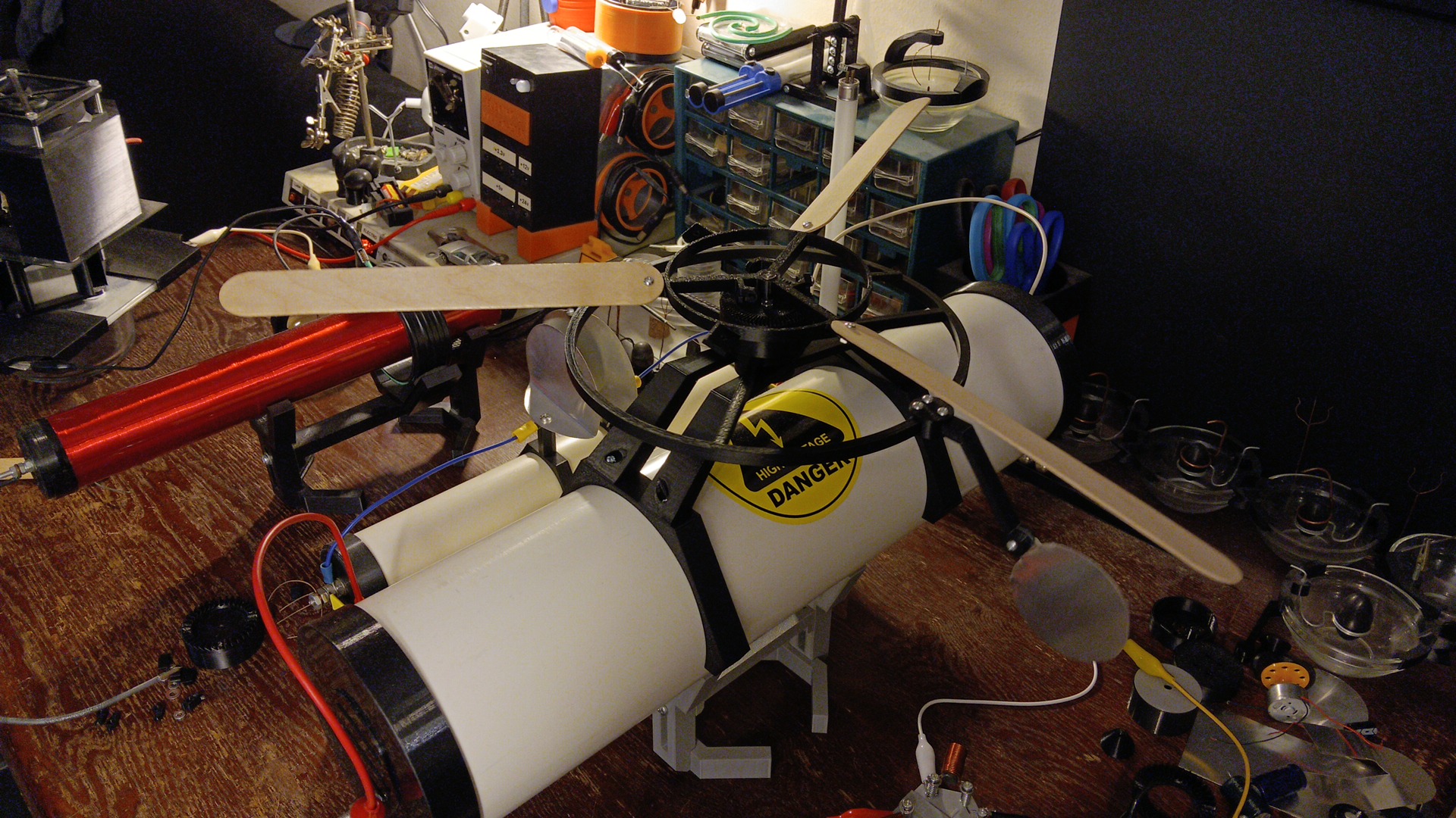
This first 'plasma / high-potential engine' is very reminiscent of an old Model-T Ford and how they sometimes sputtered and backfired; it especially even looks like some kind of new wild engine when the functional radiator fan (that keeps air slowly passing over the entire system by mechanically using the capacitors stored potential, Fig. 36) is placed on top...
ORIGINAL DISCOVERY PROCESS
Here is my original discovery process for Wireless Capacitor technology. At the time, I was again experimenting with my high-amperage WCSGTC and its unique plasma, trying LED's for the first time as extremely high-voltage plasma diodes to do 'work'...

The original YouTube 'short' (turn down volume, I used no audio filters to preserve authenticity) of the world's first wireless capacitor system, firing that very same huge capacitor right after this last picture was taken!!
YouTube Short - https://youtube.com/shorts/AQvrdWpu_VY?si=r7F6bF4WCYH_u2wH
DISCUSSION
I hope you, the reader, whom is also responsible for sharing this information to the rest of the world, can see the incredible potentials of all these truly remarkable things I have selflessly given. From water-cooled spark gap technology (which is the key to everything else I have since discovered, created and written), to brand new sciences such as Electro-tesla-mechanics and even genuine, functional glimpses into our ancient past... The truth is I'm a high-voltage archeologist, King of England (according to legend, he whom removes the sword 'electrode' from the stone shall be king - not only can I remove it, I rebuilt the device, a working lingam and wrote another journal on SGL technology that is the center of a machine which can put the sword BACK INTO the stone - so by all accounts and legends, am I not king?), but I am also, more seriously, legitimate "Tesla-coil royalty"; as the accomplishments I've attained are once-in-a-lifetime achievments - and have not since been done, at least by any living person, in over 100 years - which also makes me a living historical figure... So take this godly knowledge and information I've gone through A LOT OF TIME, TROUBLE AND EFFORT to understand and give openly to heart; and PLEASE HELP PROMOTE THESE UNDERSTANDINGS TAUGHT HERE TODAY, for it is also every life now and unborn that is in our hands at this very moment together, along with the power to make those lives far better and richer in every conceivable, applicable and knowledgable way...
Until we meet again in textbooks and history, volt on my high-voltage friends and always remember to discharge your super-capacitors, make it great, and I'll see you all again everywhere in the future!!
- John
Links
Wireless Capacitor System - Introducing the World's First WCS (Part 1)
Video Link - https://www.youtube.com/watch?v=V9X9miMIe60
Wireless Capacitor System (Part 2)
Video Link - https://www.youtube.com/watch?v=3Ipwph-RdAs
How a Water-cooled Spark Gap Works:
Journal - https://www.wcsg-science.com/#howitworks
Video - https://www.youtube.com/watch?v=mjeaYCkkxnI
Product Manual - https://www.wcsg-science.com/mini.html
How a Spark Gap Lingam Works:
Journal - https://www.wcsg-science.com/how-it-works-sgl.html
Video - https://www.youtube.com/watch?v=91cjP0m-dtU
Product Manual - https://www.wcsg-science.com/sgl.html
ELECTRO-TESLA-MECHANICS: "Tesla Coil Charge Collector" / "Electro-well" Demo
Video Link - https://www.youtube.com/watch?v=DhHB-nYIu78
ELECTRO-TESLA-MECHANICS: New "Tesla Dice"
Video Link - https://www.youtube.com/watch?v=LfIoPElOzW0
NEW ELECTRO-TESLA-MECHANICAL "SPINNERS"
Video Link - https://www.youtube.com/watch?v=JssI8mbjy_U
Bidwell's Bee - Another New Science Experiment
Video Link - https://www.youtube.com/watch?v=tOct273eW0k
This website
https://www.WCSG-Science.com
Kickstarter WCSG-Mini campaign
https://www.kickstarter.com/projects/johnbidwell/wcsg-mini
Kickstarter SGL campaign
https://www.kickstarter.com/projects/johnbidwell/spark-gap-lingam-sgl
Kickstarter Tesla Coil Charge Collector campaign
https://www.kickstarter.com/projects/johnbidwell/the-worlds-first-tesla-coil-charge-collector
High-voltage 3D models
https://www.WCSG-Science.com/models.html